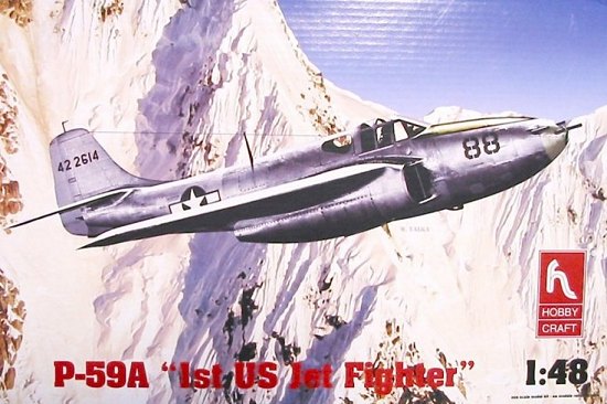
Hobbycraft 1/48 P-59A Airacomet
|
KIT # |
HC 1439 |
|
PRICE: |
$28.00 |
|
DECALS: |
3 aircraft |
|
REVIEWER: |
|
|
NOTES: |
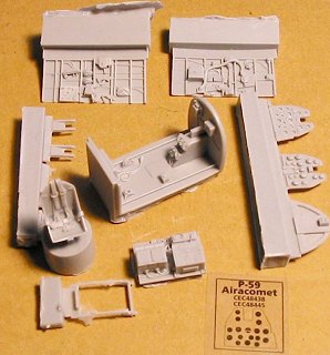
Cutting Edge CE48438 - cockpit for P-59 used |

|
HISTORY |
Some aircraft may become famous for their accomplishments. Others may be famous for merely having existed. The Bell P-59A Airacomet is in the latter category. The P-59A was America's first jet aircraft. For that reason alone, the aircraft historically significant. Though its performance was disappointing as regards speed and maneuverability, and it never fired a shot in anger during World War II, nevertheless the P-59A provided important data and experience on the care and maintenance of jet aircraft, which was invaluable when more advanced jet fighters came in to service.
Bell was a company that wanted to push the edge of the envelope from its first designs. The P-59 finds its origins in the Bell XP-52, an unorthodox fighter project created in response to USAAC Request for Data R-40C, a design competition in 1939 for a fighter with a top speed, rate of climb, maneuverability, armament, and pilot visibility, superior to those of any existing fighter. Additionally, the fighter was to have a low initial cost and be easy and inexpensive to maintain.
Bell's response was the Model 16, which had a barrel-shaped fuselage with the pilot seated in the nose, powered by a 1250 hp Continental XIV-1430-5 liquid-cooled twelve-cylinder inverted vee engine driving contrarotating propellers in pusher fashion. The wing, mounted in mid-fuselage position, was swept back at an angle of 20 degrees. Twin booms carried the tailplane, while a tricycle landing gear was fitted. Two 20-mm cannon were in the lower fuselage, with three .50 cal machine guns mounted in the front of each of the twin booms.
 A single prototype
was ordered under the designation XP-52. However this order was canceled on
November 25, 1941 and replaced by an order for another Bell design, based on
the XP-52 but equipped with a Pratt & Whitney R-2800-52 driving a pair of
three-bladed contrarotating pusher propellers, and designated XP-59.
In April 1941, Major-General H. H. Arnold visited England and was shown the top-secret Gloster E-28/39 jet-powered aircraft, powered by one of Wing Commander Frank Whittle's W2B centrifugal turbojets. Work on jet-powered aircraft was well-advanced in Britain, and similar projects were underway in both Germany and Italy. Arnold was so impressed that he asked if American engineers could be given the blueprints of the new jet engine so that they could manufacture it under license in the USA. Since the US government was being generous with its Lend-Lease aid to Britain, the RAF readily agreed.
On September 4, 1941, Arnold asked General Electric to act as the prime contractor for license production of the British jet engine because of the company's extensive experience with turbines for various industrial and aviation applications, and 15 engines were ordered.
On September 5, Bell was asked if it would build a fighter aircraft powered by the new General Electric jet engines. Bell agreed to build three aircraft and accepted a deadline of completing the first prototype eight months after signing the contract on September 30, 1941. The serial numbers of the three prototypes were 42-108784, 42-108785 and 42-108786.
 To provide a cover,
the Bell jet fighter project was assigned the designation XP-59A in the hope
that even if Axis intelligence got wind of the project, they would mistakenly
think that it was an adaptation of the totally-unrelated XP-59 piston-engined
pusher fighter. At this time, Bell engineers were already hard at work on the
pusher, but work on this was officially cancelled on December 1, 1941. The G.E
jet engine was assigned the cover designation I-A, in the hope that enemy
intelligence might mistake it for a new turbosupercharger.
By the end of November, Bell had submitted a design for a fairly conventional aircraft, with a cantilever, laminar-flow, mid-mounted wing and a fully-retractable tricycle landing gear. The aircraft was fitted with two 1400 lb. st. General Electric I-A jet engines, mounted on either side of the fuselage under the wing roots. The high tailplane was well out of the way of the turbojet exhausts, and it was fitted with a pressurized cockpit. Control surfaces were fabric covered and manually-operated, the ailerons being of the pressure-balance type with pressure seals. Although the XP-59A was primarily viewed as a test-bed for jet engines, the USAAF also viewed it as a potential combat aircraft, and it had a nose-mounted armament of two 37mm cannon with 44 rpg. The USAAF approved the initial design, and construction of the three prototypes got underway on January 9, 1942.
Without waiting for the flight of the first XP-59A prototype, the USAAF ordered thirteen service test YP-59As in March of 1942. These were to be powered by improved versions of the General Electric engine, the I-16 - later designated J-31 - rated at 1650 lb. thrust. They were to have rearward-sliding canopies in place of the prototypes' hinged canopies.
 The first XP-59A
was ferried by rail Muroc Dry Lake, California on September 12, 1942, where it
was fitted with a dummy propeller attached to its nose, in case the curious
might see it and start asking why this aircraft didn't have a propeller. On
October 1, 1942, test pilot Robert Stanley was doing some high-speed taxiing
trials with the XP-59A when it "inadvertently" became airborne for a short
time. It made its first official flight the next day, with a USAAF pilot at
the controls. This was remarkably rapid, with the first flight taking place
only 13 months after the contract had been awarded. The XP-59A weighted 7320
pounds empty and 12,562 pounds maximum loaded. Wingspan was 45 feet 6 inches,
length was 28 feet 2 inches, height was 12 feet 4 inches, and wing area was
386 square feet.
As might be expected, there were serious problems from the start. The engines were too heavy in relation to the amount of thrust they developed, while the exhaust was so hot the turbine blades regularly overheated and often broke off with catastrophic results. The maximum speed was a disappointing 404 mph at 25,000 feet. The engine installation was found to result in an inordinate amount of aerodynamic interference, and the P-59 was subject to severe directional snaking, making it a poor gun platform. Nevertheless, work on the P-59 continued unabated, and remedies were eventually found for its long list of faults.
The 13 YP-59As had more powerful 1650 lb. thrust G.E. I-16 (J31) turbojets, though they showed little performance increase over the XP-59A. Empty weight increased to 7626 pounds, while maximum speed was only 409 mph at 35,000 feet. The last four YP-59As had a heavier armament of three .50 cal. machine guns and a single 37mm cannon, which had been standardized for the production P-59A. The third YP-59A was shipped to Britain in exchange for the first production Gloster Meteor I. It was assigned the RAF serial number of RJ362/G and transferred to Farnborough November 5, 1943. The Airacomet was flown very little because of unserviceability and lack of spares. RAF test pilots found the aircraft badly underpowered, with an unacceptably-long takeoff run. In December 1943, the US Navy got the eighth and ninth YP-59As (42-108778 and 42-100779) for use in tests.
There is a famous legend about the test pilots of the XP and YP-59s flying in Gorilla suits and bowler hats, to shock pilots of conventional aircraft that ran across them over the California desert. The facts of the tale are these:
 During initial
flight testing of the P-59, Bell personnel could be distinguished by their
trademark black derby hats. Although the airspace around Muroc Dry Lake was
restricted, P-38 pilots from a nearby Army field would occasionally invade the
area to see what was going on at the "secret" base. On one flight, Bell
test-pilot Jack Woolams spotted one of the snoopers and pulled on a rubber
gorilla mask he had brought along, put on his derby, stuck a big cigar in his
mouth, then let the P-38 pull alongside. He glared back at the stunned pilot,
who quickly broke off.
Shortly before the first flight of the XP-59A, the USAAF placed an order for 100 P-59As. Since the performance of the YP-59A service test aircraft was not even up to that of conventional piston-engined fighter aircraft already in service with the USAAF and it was considered unlikely that any improvements would be forthcoming, by the fall of 1943 the Airacomet was no longer considered an operational combat type, and the P-59A order was cut to 50 on October 30, 1943, with the airplane to be used as an operational trainer.
The production
P-59A differed little from the YP-59A. Only the first 20 were P-59As. These
were powered by J31-GE-3 turbojets, although the last few were powered by
uprated 2000 lb. st. J31-GE-5 turbojets. The J31-GE-5-powered P-59A had a
maximum speed of 413 mph at 30,000 feet and 380 mph at 5000 feet. Range on
internal fuel was 240 miles, and range with
 two 125-Imp. gall. drop tanks was
520 miles. An altitude of 10,000 feet could be reached in 3.2 minutes, and
20,000 feet in 7.4 minutes. Weights were 7950 pounds empty, 10,822 pounds
loaded, 12,700 pounds maximum. Dimensions were wingspan 45 feet 6 inches,
length 38 feet 10 inches, height 12 feet 4 inches, and wing area 385.8 square
feet. Armament consisted of one 37-mm cannon and three 0.50-inch machine guns,
all mounted in the nose. In addition, two 1000-pound bombs or eight 60-pound
rockets could be carried on underwing racks.
The remaining 30 Airacomets were completed as P-59Bs. They had the uprated J31-GE-5 jets of the later P-59As, with internal fuel capacity increased by 60 gallons, increasing maximum range to 950 miles. Empty weight of the P-59B was increased to 8165 pounds and normal and maximum loaded weights were 11,049 pounds and 13,700 pounds respectively. The last P-59B was delivered in May of 1945.
Most of the P-59s went to the 412th Fighter Group of the Fourth Air Force based at Muroc Dry Lake (later Edwards AFB), where they served in the training role. The group commander was AVG ace Col. "Tex" Hill, who had just returned to the United States from a successful one-year tour as CO of the 23rd Fighter Group in China. A few P-59s were later modified and used as drone directors or manned target aircraft with a second "open" cockpit installed forward of the main cockpit.
Though the Airacomet never saw service in its intended role as a fighter aircraft, it provided the USAAF with valuable experience in the use of jet aircraft and furnished a nucleus of trained jet pilots who would take the service into the jet age.
|
THE KIT |
 There was a good
1/72 vacuform P-59 kit from Rareplanes in the 1970s that allowed a modeler to
make either a YP-59A or an XP-59A. Beyond that, the only other model of the
P-59 I am aware of is an early resin release from Collectaire in 1/48, that is
not one of their better attempts. The model is a P-59A in outline (i.e.,
squared wingtips and vertical fin), with heavily-done fabric control surfaces
associated with the XP and YP-59As. It is expensive and does not create a
model that looks as good as this one from Hobbycraft does, out of the box.
(Your editor would like to add that Karo-As produced a 1/72 short run
injection kit of the P-59 as well)
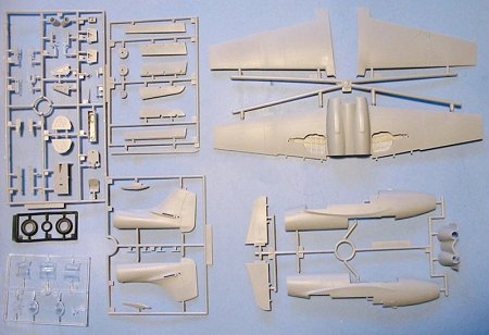
 As can be seen from the sprue scan, the kit is not very complex. the
fuselage divides in half just aft of the wing, with each of the two different
kits providing a rear fuselage with the different-shaped rudder.
Wingtips are separate as are the ailerons and flaps, for the same reason.
 The cockpit is very
simple, consisting of a floor and rear bulkhead, seat, control stick,
instrument panel and a "radio box" to fit behind the headrest. If you build
the model with the cockpit closed up, this can be done to an acceptable level
with some scratchbuilding.
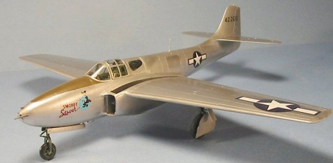
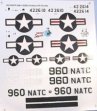
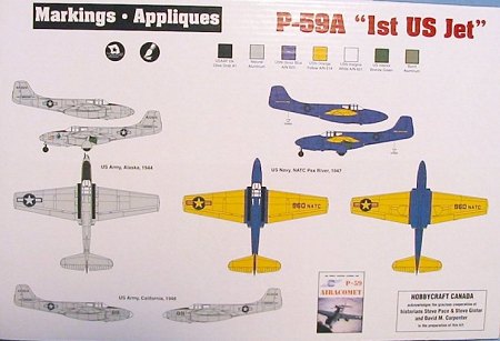
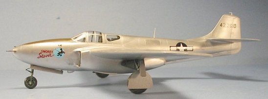
Decals for the P-59A kit include two aircraft of the 412th Fighter Group, one
of which - with nose art of "Smokey Stover" - was the P-59A that
 participated in winterization
trials in Alaska in 1945. The third is a colorful Navy test aircraft from the
late 1940s, based at NATC Patuxent River. These are - like all new Hobbycraft
decals - excellent.
Aftermarket:
Cutting Edge already has a truly wonderful resin cockpit, created by "Mr. Cockpit" Scott Battistoni, for the kit. I think I am safe in saying that I am the only modeler in the world to have recently sat in the cockpit of a P-59A - that being the one that Planes of Fame is restoring to flight status out at Chino - and this cockpit by Cutting Edge looks like the real thing, hit with shrink spray. The cockpit is easy to build up, fits perfectly, and transforms the model from a "nice three-footer" (i.e., looks good at a distance of 3 feet), to a model you won't mind having the judges look over with their penlights. I highly recommend it as good value for the money.
|
CONSTRUCTION |
The best attitude to
bring to this project is to consider the kit a limited-run kit. You will have
to test-fit and modify just about everything that's in the box.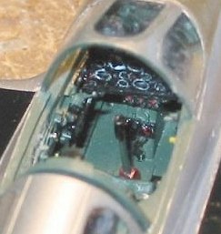
I began by painting the CE cockpit, the surrounding area of the fuselage, the wheel wells, gear and gear doors in "Bell Green." This is actually a color very close to US Medium Green FS34092, and that is what I used, from Gunze.
While that was drying, I glued the fore and aft sections of each fuselage half together. The join line unfortunately is not on a panel line, so you will be using quite a bit of Mr. Surface 500, reapplied as necessary, to get rid of that seam.
While the fuselage halves were setting up, I assembled the 3-piece wing. I found when I went to attach the ailerons and flaps that I had to sand and re-shape the leading edges of the flaps and ailerons so they would fit to the wing right. These are not designed to be displayed in any "dynamic" position, but are merely separate because the YP-59As had fabric control surfaces while the P-59As had metal surfaces. In fact, the P-59 has a spring-loaded stick so that the flying surfaces are not drooping in any way when the airplane is sitting on the ground.
I also suggest you sand the top of the wheel well roof and adjacent area of the wing to ensure a tight fit.
I went back to the cockpit, detailing the parts, and then assembling it. I glued it in position in the fuselage, and also attached the nose wheel well. Just looking at how much fuselage was behind the line of the main gear, I knew the model was going to have trouble nose-sitting. I therefore filled the area ahead of the cockpit tub and above the wheel well with lead fish weights, then - after the fuselage was assembled - I filled the area behind the wheel well beneath the cockpit with more fishing weights. As it turned out, that wasn't enough. I therefore suggest that when you do yours, you fill the area of the fuselage directly aft of the cockpit (but ahead of the line of the main gear) with more weight, and also the area of the fuselage between the engines, ahead of the line of the main gear. The real airplane sits slightly tail-low (another problem to be dealt with when doing the model), so all of this weight should just keep it on its nose wheel most of the time. The splitter plate in the intake is too thick and too flat. Sand it down by half, then glue it so that it conforms to the curvature of the fuselage there.
 I test-fitted the
wing sub-assembly to the fuselage sub-assembly, and discovered that as it
comes from the box, the wing will lose the correct dihedral without some
further modification. I sanded down the inner edge of each upper wing a bit,
until I could test-fit and apply enough pressure to get the wing at the proper
angle. I then glued the lower center section to the fuselage with regular
plastic cement. I pushed each upper wing into proper position, ran cyanoacrylate glue along the seam, and hit it with accelerator. The wing was
in correct position. I then attached the horizontal stabilizers and
elevators, then went over all joints and seams with Mr. Surfacer. As
expected, I had to reapply Mr. Surfacer three times to the seam created by the
joint of the fore and aft fuselage parts, to get it to finally disappear.
I also used some Evergreen sheet to make better "fairings" of the engine intake to the fuselage, per photographs of the real airplane. As the kit comes straight from the box it will not look really right otherwise. This required a bit of carving of the Evergreen sheet, application of Mr. Surfacer, and sanding down.
Also, the model has a slightly "pebbly" surface to the plastic parts. You can leave this alone if you are going to do any of the versions that are not in Natural Metal Finish, but you will have to sand down the whole model with fine grit sandpaper, and then polish it out before proceeding to painting.
|
CAMOUFLAGE & MARKINGS |
Painting:
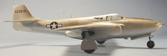 I attached the
Futured canopy with the sliding center portion in the closed position, masked
off the clear areas, then shot the canopy with Medium Green for the interior
color. I then shot the anti-glare panel with Gunze-Sangyo Olive Drab, and
masked that off. I masked off the wheel wells and was ready for the NMF
painting.
I shot the whole model with SnJ aluminum. I waited about 20 minutes, then applied some of the buffing powder to various panels and buffed them out. I let the model then cure overnight, then masked off various areas and used different Testors Model Master Metalizer colors to give a "multi-hue finish," sealing each of those as I completed them before going to the next.
Decals:
The kit decals went down with no problem whatsoever.
|
FINAL CONSTRUCTION |
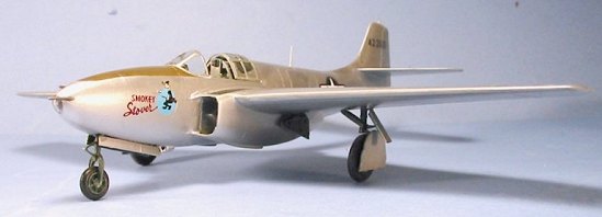 It was at this point
that I discovered the main gear legs are 1/8" too long, while the nose wheel
leg is 1/8" too short! The main gear was simple to fix. I had to drill out
the nose gear leg, and then attach a piece of Evergreen rod to make up the
shortness.
I used the kit-supplied rubber wheels because I had no alternatives, but I attached them with white glue. The minute someone creates some resin wheels for this model, I will replace them since I have already gone through the heartbreak of having to amputate the feet of my F-7F Tigercat at the ankles, the result of the interaction of vinyl with polystyrene.
|
CONCLUSIONS |
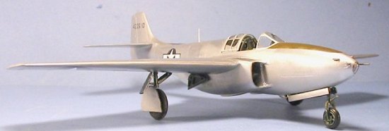
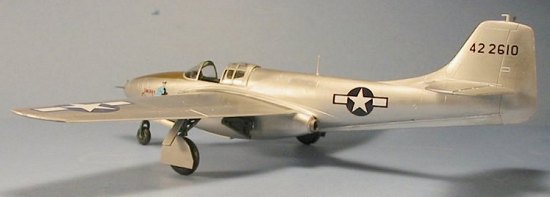
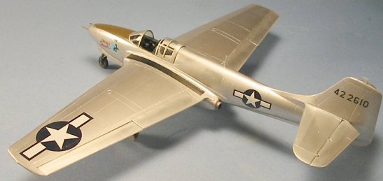
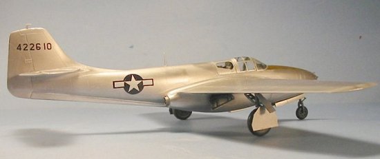
The model looks good with canopy closed or open. As you can see from the photos I have included here of the model with the canopy closed, you can get away without using the aftermarket cockpit. But if you want to open it up, you need that cockpit. This is a good-looking model, and - to my mind - the nicest thing Hobbycraft has done since the P-26. I am hopeful for the Panthers and Cougars should they ever do them.
Looking at this model makes me impatient for the day I will be sitting in the open tail position in "Photo Fanny," the Air Museum's B-25, when Steve Hinton brings the recreated "Smokey Stover" in for its closeup - it might even be next year!
April 2003
Copyright ModelingMadness.com
Kit Courtesy of my Wallet
If you would like your product reviewed fairly and fairly quickly, please contact the editor or see other details in the Note to Contributors.