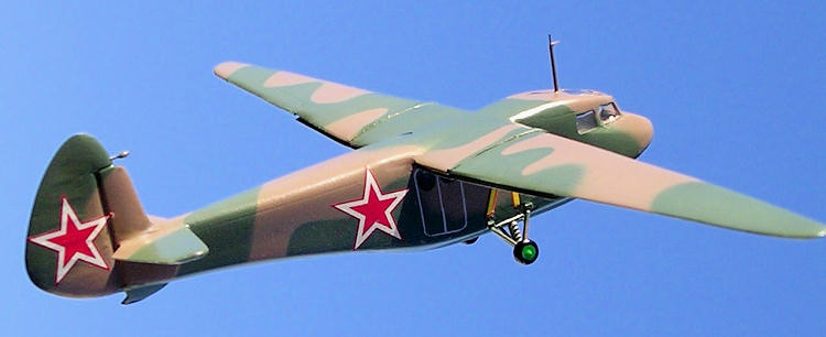
Vac Wings 1/72 Antonov A-7 Glider
| KIT #: | ? |
| PRICE: | $10.00 |
| DECALS: | None |
| REVIEWER: | Carmel J. Attard |
| NOTES: | A vac form kit, no decals issued. |

| HISTORY |
The A-7 was an
assault glider that was for a time obscure to Western observers and historians.
It was an important Soviet glider and as such deserves its place in history. The
A-7 was announced in December 1940 in a design competition for an assault
glider. Also known as the RF-8 in the Red Front series of gliders for the Soviet
Air Force, it was designed by Oleg K. Antonov and after it was declared the
winner of a design for military transport gliders it became the prototype for
the subsequent A-7. The A-7
 was to be the first Soviet transport glider to
achieve production status. The assembly plant was in
The A-7 was a
remarkable clean design, all-wood construction with partial fabric covering on
wing areas and tail-planes. The core of the structure was the fuselage, which
was almost of the pod and boom type with an enclosed cockpit and accommodation
for a maximum of 9 troops in virtually windowless compartment. There were two
pairs of double doors; one was forward on the port side and the other aft on
starboard side. The tailskid landing gear included manually operated retractable
main units, stowed in wells in the lower fuselage sides.
The standard tug was
the Tupolev SB-2, Ilyushin DB3 or the Il-4. The maximum towing speed was a high
300Km/h. The A-7 saw limited service behind German lines in WWII and was used
primarily to supply or land partisans or sabotage groups. Itís best known action
was the supply flights to the
| THE KIT |
 The A-7 is a vac-form
kit molded on a single sheet of white styrene and a small clear part for the
canopy. Issued by Vac Wings 72 of
| CONSTRUCTION |
 The kit contains
around 19-vacform parts and one clear part for the cockpit canopy in case one
desires to use it, and this has clear frame detail on it. The kit fuselage and
wing parts also have fine surface detail. Construction follows the now standard
adopted for vacform kits. Each part is first lightly scored around on the single
sheet using X-acto blade, which is then snapped from the sheet. Fuselage and
wing parts are sanded perfectly flat so that the edges mate. A 400 wet and dry
sand paper tape mounted (double sided) to a piece plate glass for a smooth
surface. Pieces are trial fit together before affixing with liquid glue. Parts
are checked with plans issued. With the exception of the rudder and tail-planes
all the other items matched with the drawings.
The rudder needed an
extension of 3mm at the rear which was a gradual addition making a bigger rudder
area. This is best done by tracing the rudder on a 0.4mm plastic card that is
then inserted between the kit fuselage parts at the rudder area and fair with
filler at the stepped rear. 7 round windows and 2 semi circular ones were
drilled and shaped to conform with the drawings given, these were at side of
fuselage, under the fuselage, and one on the roof. The forward crew area was
built up from the kit parts and a floor area for the passenger section was made
from plastic card that was then inserted inside the fuselage compartment. A
bulkhead separated the two co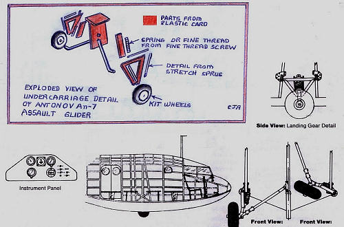 mpartments. 4 double bench seats at sides and two
single bench seats at center of fuselage were added inside the passenger area
while a pilot seat, rudder pedals, control stick and instrument panel added to
the front compartment. Close study of the landing gear detail indicated the
position of the retractable undercarriage bay and its function. This required
opening two rectangular panels under the fuselage and adding a central dividing
wall, which secured the undercarriage legs. The drawing I made shows in
simplified detail of how I built it from kit wheels, plastic card, spring/thread
and other detail from stretch sprue.
The wing parts also had the flaps separated, which were then assembled, in partially lowered position. The tail planes were extended by 3mm in order to match them with drawing and ensuring that the elevator parting was 90 degrees to the axis of the fuselage when attached to it. Aerial mast and rudder ballast were made from metal pins cut to size and fixed with super glue. As for the canopy, I decided to put away the one issued and as the window apertures were small I carefully cut and shaped these with a sharp-pointed Exacto blade and needle files so that Kristal Kleer could make the glazing. A front eyehole for tying the tug cable was made from a small piece of bent wire.
| COLORS & MARKINGS |
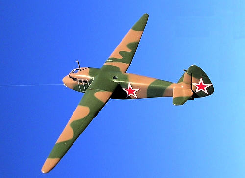
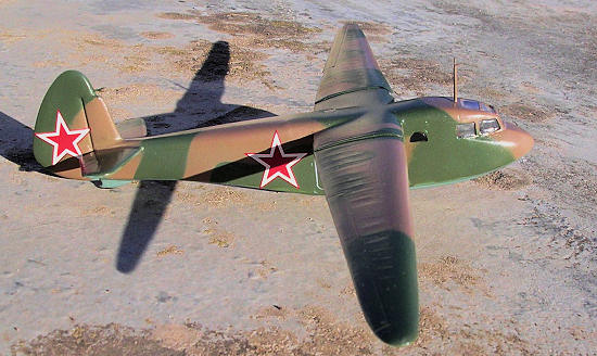
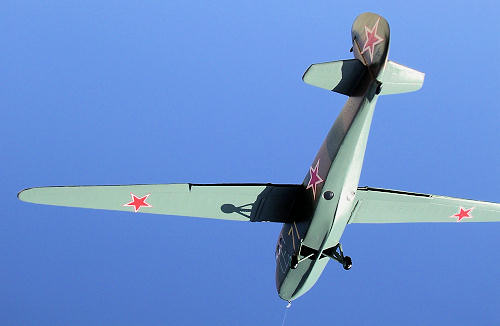
The operational
camouflage was olive green and dark earth camouflage to all upper surfaces and
pale blue underside. The camouflage had feathered edges. For night operations
the undersurfaces were matt black and were without wing insignia. A
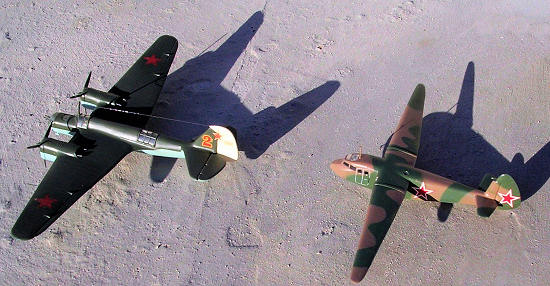 yellow code
number that was outlined in black appeared on the forward fuselage sides. Red
stars outlined in white added to four positions. The pale blue underside of
wings carried solid red stars. The entire interior was light gray while seats
and straps were brown and dirty white respectively. The kit was finally given an
overall coat of semi gloss varnish.
| CONCLUSIONS |
February 2010
If you would like your product reviewed fairly and quickly, please contact me or see other details in the Note to Contributors.