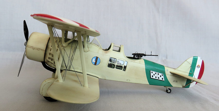
Classic Airframes 1/48 IMAM Ro.37bis
| KIT #: | |
| PRICE: | |
| DECALS: | |
| REVIEWER: | Michael Rohde |
| NOTES: |

| HISTORY |
Meridionali ( Officine Ferroviarie Meridionali) became involved in the Italian aircraft industry in 1923and began manufacturing activities in earnest two years later by building Fokker designs under licence. Subsequently, after two years operating under the name Romeo, the company title ĎIndustrie Meccaniche e Aeronautice Meridionalií ( IMAM) was adopted in 1936.
In 1934, the design and production of a two seater fighter / reconnaissance biplane took place under the designation Romeo Ro 37. A unequal-span single bay biplane of mixed wood and metal construction, the design included fixed tailwheel and main landing gear with all wheels provided with speed fairings, a braced tail unit featuring a variable incidence tailplane , and accommodation for pilot and observer in tandem enclosed cockpits. Power was provided initially by a 700 p Fiat A 30 RA Vee engine.
 A improved version of the Ro 37 called Ro 37 bis
introduced optional powerplants comprising either the 560 hp Piaggio P.IX or P
.X supercharged 9 cylinder radial engine. Both models proved popular for their
day and production of the Ro37 and Ro 37 bis exceeded 160 and 475 aircraft
respectively. Export orders were received from Afghanistan Hungary ,and from
countries in Central and South America..
Both the Ro 37 and 37 bis variants were involved in the Spanish Civil War from October 1936 and extensively used by the Regia Aeronautica during Italyís invasion of Abyssinia between October 1935 to May 1936 and during the occupation of that country until 1941.
When Italy entered the Second World War, some 275 Ro 37 bis aircraft were in service with the Regia Aeronautica , and these saw front line service in the East and North African campaigns and in the Balkans. Front-line aircraft carried two fixed forward firing synchronized 7.7 mm machine guns and one similar gun on a trainable mount in the rear cockpit. For ground attack missions up to 180 kg of bombs were carried on a fuselage bomb rack.
After their withdrawal from first line service they were used in a variety of tasks, but all remaining aircraft had been retired before Italyís armistice with the Allies on 8th September 1943.
| THE KIT |
 Being a typical CA kit , we also get a set of resin
parts and a nice PE set. The plastic parts are moulded in light grey plastic and
are arranged on four frames labelled A to D. There is one frame carrying 5 clear
parts for the extensive cockpit glazing. Parts count is 51 on frames A to D, and
11 resin parts in a small sealed plastic bag. Film is provided for creating very
nicely detailed instrument panels ( 2 options there).
Surface detail overall is good , panel lines are crisp. There are no locating pins and careful dry fitting before cementing is recommended. Decals are made by MicroScale and of good quality. Options are available for three aircraft:
Gruppo 4-G-12 Spanish Nationalist Air Force ,ca 1938
115a Squadraligia O.A. Tamet, North Africa ,ca Oct 1940
26th Gruppo ,105th Squadraligia Ethiopia ,ca 1935.
The instruction sheet is set up into 12 steps of construction and are easy to follow.
| CONSTRUCTION |
Being a low pressure injection moulded kit time and
effort needs to be put in to inspect all parts closely and remove any seams ,
flash and the occasional sink mark. This is what I did with all the parts and
afterwards attached these on pieces of cardboard with strips of masking tape.
Important not to forget numbering the
 bits according to the parts diagram in the
instructions!! The resin parts were carefully removed from their casting blocks
and inspected for any air bubbles ( which were filled with CA glue and cleaned
up). I added stringers and additional tubing to the keel surfaces and fuselage
floors ( esp. In the rear behind the observerís gun position since that area is
quite visible once the fuselage is closed up).
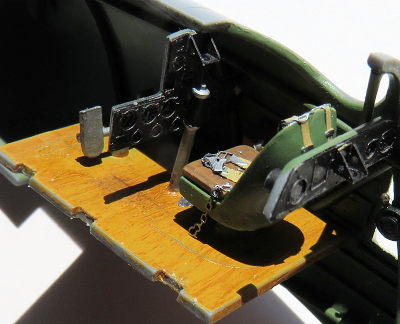
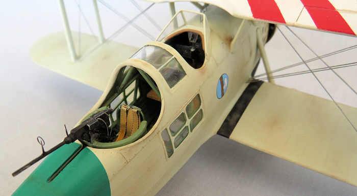
I painted all the components required for the cockpit interior, assembled the instrument panels , attached the PE seat harnesses to pilot and observerís seat and painted these. The cockpit floors were originally made of wood and I made an effort to create the wood grain effect using oil paints. After the oils had dried I glued the pilot / observerís seats, control column and rudder pedals onto the cockpit floors and attached the additional harness parts as per instructions. The observerís compartment glazing was fitted before I glued the internal framework into place.
Now we arrived at the first tricky part of the assembly process: Test fitting the front and rear part of the cockpit in situ and try to check the alignment of the fuselage shells. This I tried to achieve by using little blobs of play dough and masking tape to secure these parts as good as possible and that helped to check if there was any interference when putting the fuselage shells together. Once I was sure that there were no further surprises in store I glued the cockpit internals into place using CA glue. The instructions do provide a diagram for the positioning of parts in this particular step.
The fuselage shells were then mated together and some putty was required to correct seam lines. Once that was done , I re-engraved some of the panel lines lost in the process. The lower wing was taken care of next. After the glue has set and the seams along the leading and trailing edges were cleaned up, I test- fitted the lower wing. The overall fit was surprisingly good and I went ahead and fitted the lower wing. Small gaps were filled and sanded.
Then I test fitted the large rectangular piece of glazing in the cockpit floor. A bit of careful adjustment was needed to achieve a good fit. Before I moved on to the next challenge ( fitting the cabanes struts and the upper wing) ,I glued the horizontal tail plane and supporting struts into place . Again, no locator tabs , so test fitting and adjusting was necessary to ensure a good fit.
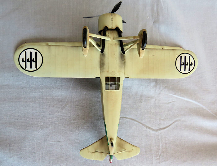 In the meantime I assembled the upper wing shells and,
after the glue had set, sanded the leading and trailing edges. That done, I
glued the two halfes of the generator housing together and cleaned up the seams.
Test fitting was required to ensure the best possible fit on the starboard
leading edge. Prior to fitting the struts and cabanes I prepared the anchor
points for the rigging by drilling holes with a .10mm drill. No diagram is
provided in the instructions . One has to study photos of the aircraft available
on the net to get an idea where to drill.
We have locator pins on the struts and cabanes and shallow holes where these parts are supposed to be glued into place on the wings. There is a diagram showing the alignment of the cabanes , but one has to rely on measuring the distance between the locator holes ( using a compass) to determine the exact angle of adjustment . The same does apply for the struts.
Then came the moment of truth!!
I glued the struts into place checking and re -checking the angles until the glue had set sufficiently to leave things alone for a while. Before I moved on to fitting the upper wing I test fitted the wind screen and found that it was actually a bit too big and bulky and so I decided to scratch build a new one using .40 mm Evergreen sheet. Once in place , I painted the frame and the fuselage decking behind the windshield prior to fitting the upper wing. With that item done and dusted I returned to the matter of fitting the upper wing.
In order to do that I fixed the upper wing assembly on a piece of cardboard using masking tape and placed the model on the wing checking how good contact was between struts and wing surfaces. As expected , careful re-setting Ė especially the outer struts- was necessary for correct alignment. That was done by using a scalpel blade to achieve a clean separation and re- cementing the struts accordingly. Another check was carried out before I glued the upper wing onto the struts and cabanes and any remaining small gaps were filled with CA glue and carefully sanded where necessary.
The next big item was the landing gear. The kit does
provide a nice PE set of spoked rims if the non- spatted wheel option is chosen.
In this case I decided to do the spatted wheels option which does not require
the full set of PE bits . Only one part ( PE 8) is necessary. Once the wheels
were assembled and painted , I test fitted these into the spats before glueing
the shells together. The landing gear support struts
 (2 main and 4 stabilizer
struts) were glued into place and , after giving sufficient time for the glue to
set, I attached the wheel spats to the structure.
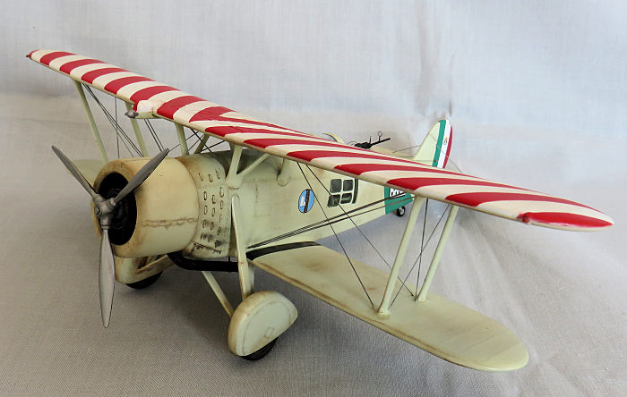
Last but not least it was the engine and associated parts turn: Here I had no real issues apart from having to remove some material from the cowling to provide room for the rather substantial exhaust tubes. The engine itself received a set of ignition leads ( made of thin copper wire) and a distributor ring ( made of .2mm Evergreen rod) I also fashioned a exhaust collector ring from stretched sprue which also served as a support for the exhausts.
Once the engine and the cowling was mated another test fit was required to see what the alignment with the fuselage was like. There is a opening provided but that hole needed opening up to get a bit more leeway to align the cowling correctly.
By the way: Another important thing which needs to be done is to scoop out the area on the bottom of the fuselage in order to be able to accomodate the exhaust in such a way that the exhausts can be placed in the correct position with space in between the struts and lower fuselage.
Usually I do the rigging of the model after painting has been done , but in this case I tried a different approach. I did the rigging prior to airbrushing the model. The advantage of doing it that way is that one does not need to remove any paint from the anchor points and it was easy enough to paint the rigging wires with Tamiya flat aluminium later.
| COLORS & MARKINGS |
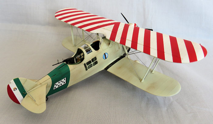
Now it was time to hand paint the frames of the fuselage glazing followed by careful masking of all clear parts ,the cockpit and the wheels. I decided not to apply the decals provided for the upper wing, but to use masking and airbrush instead.
This was done in the following manner: first a coat of
Tamiya flat white followed by strips of masking tape applied in the pattern as
shown in the instructions. To avoid overspray while using Tamiya red I masked
off 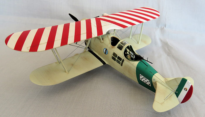 the rest of the model using strips of paper towel held in place by masking
tape. After sufficient drying time all the masking was removed and the upper
wing was given a thin coat of Tamiya clear gloss.
The upper wing was masked off and I airbrushed the rest of the airframe with ivory white ( I made up that colour by adding a tiny amount of Tamiya flat yellow to Tamiya flat white). The engine cowling was airbrushed as a separate item and attached to the fuselage later. All the rigging wires were painted with Tamiya flat aluminium and the entire model received a final coat of Tamiya clear gloss as a base for the decals.
The decals went on just fine Using Microsol made them wrinkle a bit and I had to watch this space ( esp. the large fuselage bands ) and used a brush moistened with Microsol to carefully remove the wrinkles. When the decals had dried I gave the entire model a sealing coat of Humbrol satin and left to dry overnight. The weathering was done with pastels and Tamiya Accent panel liner black and brown.
| CONCLUSIONS |
This is not a shake and bake kit but with patience and some experience with building bi plane kits one can build a nice example of a Italian interwar period aircraft.
14 May 2020
Copyright ModelingMadness.com
If you would like your product reviewed fairly and fairly quickly, please contact the editor or see other details in the Note to Contributors.
Back to the Main Page Back to the Review Index Page Back to the Previews Index Page