| KIT #: | 172 |
| PRICE: | approximately €12.00 when new |
| DECALS: | None supplied |
| REVIEWER: | Carmel J. Attard |
| NOTES: | Vacuform less decals or detail parts. |

| HISTORY |
The He59 was designed in 1930 from a requirement issued by the
still-secret German Air Force for a torpedo bomber and reconnaissance sea plane
able to operate with equal facility on wheels or twin- float landing gear. It
was an equal span biplane with an unstaggered two-bay wing cellule and was based
on a rectangular section fuselage of fabric covered welded steel tube
construction faired at top and bottom into rounded shapes that give the fuselage
an oval appearance in frontal elevation.. Flying surfaces were fabric covered
tail unit and fabric covered wooden wings. Floats were single step wooden
construction. The
 engines were installed in nacelles carried by interplane
struts; each drove a four-bladed, fixed pitch wooden propeller. In due course
the landplane variant was not proceeded with.
The He-59B-3 was intended for long-range maritime patrol tasks with
auxiliary fuel tanks and reduced armament of just two machine guns. In 1936 the
Luftwaffe which was by then revealed to the public the previous year
commissioned its first coastal floatplane units. Soon after,
| THE KIT |
 The 1/72 scale Airmodel kit No172 comes sealed in a polytene bag
containing 2 sheets of soft white styrene with all the kit parts in vac form.
There is a 4 page instruction sheet and a 2 page side view in black and white
giving details or suggestions of typical markings of several examples. The
instructions have detail history and method of construction. The folding centre
pages have detail drawings of assembly views and section scrap views to help
with interior decorating. No scale plans were provided and I found it very
essential to have plans, thanks to plans that I had from past issue of Aviation
News although this lacked adequate rigging detail. The kit contains no struts in
spite that there are so many to go on the kit. One therefore has to provide his
or her own. I made mine from Contrail struts supplied by Roll Models. These were
cut to correct length given in the instruction sheet. No decals are provided
with the kit. The kit is quite detailed particularly the fabric ripples on side
of fuselage and wings. There are several moulding pips that need to be removed
prior to assembly. The good thing about this model was that the plastic was very
soft and welds very well with Humbrol liquid cement.
| CONSTRUCTION |
Being a vacform kit, one can follow any procedure found in previous vac
form kit reviews as this is absolutely a standard one. The only difference being
that since the kit is of a fairly large size it would benefit if a large sanding
wet and dry paper is attached with a double sided tape to multiple plywood of
reasonable length and width to match the size of the model. As with all vac
forms, the most daunting part of the kit is removing the pieces from the backing
sheet.
I trace around all the parts with a soft pencil, then scribe around them
with a new blade in my knife.
I cut at a 45 degree angle Items like the cabin floor,
and those for the front gunner and rear observation compartment, these are all
cut from the surplus backing plastic. Engine mounting struts were made
 from
Contrail struts as mentioned earlier. These were cut to conform to width and
length as per drawings given. One can use the kit parts to make the propeller
blades in which case once the props are cut and shaped the rear void is filled
with filler. One can purchase a set from mainstream suppliers as in fact I did.
In brief the sequence of assembly is to build the fuselage complete with
all the interior details added. The two engine nacelles complete with side
exhausts are then assembled and placed aside. The wing halves are sanded to
correct thickness, added interior webbed stiffeners and glued together. The
fuselage was then cemented to lower wing and the floats are then set at relative
position using scrap piece of wood of suitable height and using a card template
and the length of bracing struts are checked and measured. The struts are
trimmed to suite and cemented in place. Procedure was repeated to inboard struts
and again for the outside struts. The upper wing is then set to correct position
relative to the fuselage and with a template the length of outboard and
interplane struts are checked. Procedure is repeated for the cabine struts and
for the nacelle struts. Assembly was allowed to set for about 12 hours. Tail
plane complete with struts was cemented in place.
 In the end all the outside details as the generator to cabine struts,
searchlight, trailing aerial tube, wing ladder, DF loop, and ring mounted
machine guns are all added to the fuselage. Anchor points made from metal wire
were also added to the floats. A wind screen is cut from a piece of clear
acetate, bent to shape and fixed to the front cockpit. Careful study was made to
the rigging that ties the wings together. Tiny holes were drilled at the
different positions and the wings were literally sewn using invisible thread.
Rigging was proved to be the most difficult job with this kit. Because of their
thickness the wings are hollow so that when you drill a hole right through the
surfaces, this would be a problem of threading the flexible invisible thread
through both holes. This is so as it would be difficult to connect with the
second hole through an empty space inside the wing. Only through perseverance
and patience I finally managed. The wing rigging was a combination of single or
double wires. For reference the Aviation News scale plans were definitely of no
help and the best source was finding enough close up pictures from internet web
sites. When complete the kit now took a sturdier shape an
 d I took a deep sigh of
relief.
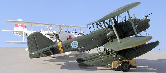
In line with every floatplane model that I build I made my own beaching trolley for the heavy seaplane. Basically the trolley was constructed from various plastic card shaped pieces and wooden blocks using scale plans which I first drawn to 1/72 scale and also contemporary reference photos. They seemed to be strengthened with metal on the sides and at the bottom. A set of wheels of correct shape and diameter were picked from the spares box. The floats would not sit directly on wood but on rubber ends at the rear ends. One should note that there is a castoring wheel at the rear of each float. This is in the form of an extendible wheel within a hollow bar. This assembly I did not add to the kit in time for the preparation of this write-up so that I could figure out a method whereby the end wheels are slotted in the rear of the float and remain detachable. The trolley was given a coat of varnish.
| COLORS & MARKINGS |
The engine front was dark grey; prop blades light grey; the floor was
RLM 02 Grey and sat pan in aluminium while the seat back brown leather. Control
column was black. Gunner seat was brown with RLM 02 gray tubing.
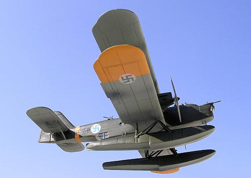
As I have decided to make a Finn AF example this was finished in
aircraft grey undersides. Unlike the German machines the Fin AF ones did not
have splinter camouflage but was
olive green RLM 72 upper surfaces. Finn AF
swastika and registration letters and numbers came from spares decal box.
| CONCLUSIONS |
This is definitely not a kit for the beginner but certainly not out of
reach for the average kit modeller with some experience with vacform kit making.
The
kit will not therefore be difficult to build for those who have experience in
this kind of kits. I always enjoy building a vac form kit now and again and the
trick is never to rush to get the job finished quickly. The He59 has a definite
graceful shape and I already made my first steps of assembly with another He59,
yes sir… a vac form type once more but this time from a different make.
November 2008
Copyright ModelingMadness.com. All rights reserved. No reproduction in part or in whole without express permission.
If you would like your product reviewed fairly and quickly, please contact the editor or see other details in the Note to Contributors.