| KIT #: | AM-067 |
| PRICE: | 18.50 Euros |
| DECALS: | Three options |
| REVIEWER: | Spiros Pendedekas |
| NOTES: | Some scratch building required |
| HISTORY |
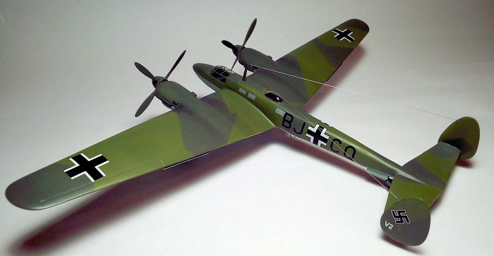
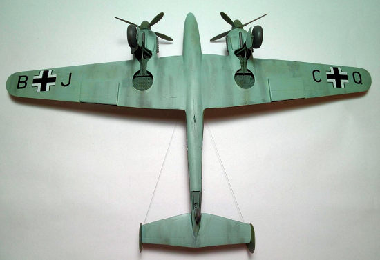
The Adolfine was a long-range reconnaissance aircraft designed in the late 1930s. It looked like an enlarged version of the Messerschmitt Bf 110. It was not put into production; just three Me 261s, V1 (BJ+CP), V2 (BJ+CQ) and V3 (BJ+CR) were built and used primarily for testing and development purposes.
The intended goal of the Me-261 project was for an example of the aircraft to carry the Olympic flame from Garmisch-Partenkirchen, Germany (site of the 1936 Winter Olympics) to Tokyo, Japan for the 1940 Summer Olympics in what would be a record-breaking nonstop flight (5870 mi / 9445 km). The plan captured the imagination of Adolf Hitler at an early stage in its design and in tribute, the aircraft carried the unofficial name: Adolfine.
The Me 261 incorporated a number of features which were highly advanced for its day. The single-spar all-metal wing was designed to serve as a fuel tank and its depth at the wing root was only slightly less than the height of the fuselage. The fuselage was of virtually rectangular section with space for five crew members, consisting of two pilots seated side-by-side with the radio operator directly behind in the front compartment, while a navigator and a flight engineer were housed in the rear fuselage under a stepped, glazed station.
Power came from four Daimler-Benz DB 601 engines, coupled together in
pairs in a “power system” known as the DB 606, weighing 1.5 tonnes apiece and
debuting in February 1937. The DB 606 “power systems” were originally developed
for both the “single”-engined Heinkel He 119 high-speed reconnaissance aircraft,
and the H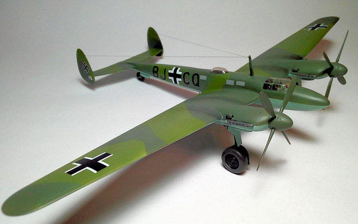 einkel He 177 strategic bomber, but the Me 261’s design housed the DB
606 “power systems” in nacelles that afforded significantly better access for
maintenance and ventilation of the “twinned” DB 601 component engines in each
one, than the Heinkel heavy bomber possessed. Each pair of engines drove a
variable-pitch propeller, intended to be a pair of counter-rotating propellers
(as the He 177A had used for its fourth prototype onwards) with each four-blade
propeller driven through a gearbox shared between the “twinned” DB 601 engines
forming the “power system”, generating 2,700 PS (1,985 kW) each.
einkel He 177 strategic bomber, but the Me 261’s design housed the DB
606 “power systems” in nacelles that afforded significantly better access for
maintenance and ventilation of the “twinned” DB 601 component engines in each
one, than the Heinkel heavy bomber possessed. Each pair of engines drove a
variable-pitch propeller, intended to be a pair of counter-rotating propellers
(as the He 177A had used for its fourth prototype onwards) with each four-blade
propeller driven through a gearbox shared between the “twinned” DB 601 engines
forming the “power system”, generating 2,700 PS (1,985 kW) each.
The Me 261 had a conventional landing gear with unusually large and bulky low-pressure tires, much like modern day aircraft tundra tires, which prevented the aircraft from becoming bogged down on rough grass landing strips. The main gear’s design appears to use main struts that rotated through 90° during their rearwards retraction sequence, with sizable main wheels resting atop the retracted struts (similar to those used on production examples of the contemporary Junkers Ju 88). Even the Me 261’s fully retractable tailwheel possessed a larger-than-average, low-pressure pneumatic tire.
Construction of three prototypes began at Messerschmitt’s Augsburg works during the spring of 1939, but progress was slow due to the realisation that war would probably soon break out and the 1940 Summer Olympics would be cancelled. The Me 261’s original design brief as a long-range reconnaissance aircraft had been forgotten; now viewed as non-strategic, it was nearly abandoned with all work stopping in August 1939.
The Air Ministry subsequently realised that the Me 261 could still be a useful vehicle for evaluating long-range operations, and work resumed in the summer of 1940.
Me 261 V2 (BJ+CQ)
The first flight of the Me 261 V2 was in early 1941. Official thinking now saw the Me 261 as a long-range maritime reconnaissance aircraft. The Me 261 V1 was badly damaged during an Allied bombing attack on the Lechfeld Air Base in 1944 and eventually scrapped.
| THE KIT |
This Airmodel kit was given to me as a present from a friend many years ago. Being a vac, for sure, is not exactly for beginners. It offers nice quality vac styrene parts and really great resin detail parts, looking very promising and very impressive indeed!
The beautifully made vac styrene parts include fuselage (two options are provided: V1 or V2/V3), main wings, rear wing, fins and engine nacelles (with their respective square looking air inlets).
 Resin parts include instrument panel, 2 seats, one control column,
landing gear legs and wheels, 4 outboard cylinders exhausts, two propeller hubs
with their corresponding keyed 4-blade sets and an antenna mast . Those resin
parts are very well made (occasional pinholes are here) and add a lot to the
looks of the model.
Resin parts include instrument panel, 2 seats, one control column,
landing gear legs and wheels, 4 outboard cylinders exhausts, two propeller hubs
with their corresponding keyed 4-blade sets and an antenna mast . Those resin
parts are very well made (occasional pinholes are here) and add a lot to the
looks of the model.
Some “simple” or not so simple parts are not there and have to be
scratchbuilt. This is especially true for the wing flat air inlets, the inner
engine cylinder rows exhausts, the MLG retraction cylinders, the underbelly loop
antenna, the crew windows etc.
Instructions are as spartan as they could be, but are clear. A nice big 3-view
plan is provided, along with some cockpit schematics and similar relative info.
With careful studying, net browsing and a little imagination, you can keep
walking…
As said above, you can build the V1 or V2/V3 prototype, their most obvious difference being the aft part of the fuselage, with two different aft sections provided.
Regarding the V3 (BJ+CR), it looks that, from the scarce info/pic(s) and assumingly nonexisting 3D view, it had the same outline as the V2 (with different crew arrangement), so the only change would be the numbering.
Decals are not provided, but are generic, so you can take them from
generic Luftwaffe decal sheets and/or leftovers from your decal dungeon.
Upon receiving this kit, a bizarre urge to build my first vac conquered me! So
off I was, a dozen years ago!
Had to stop, as I had to move to my new house, set my new workbench up, then my
beloved kids arrived and so time flew....
Started to gradually reconnect with modelling hobby in 2019 and decided to
finish this beauty.
| CONSTRUCTION |
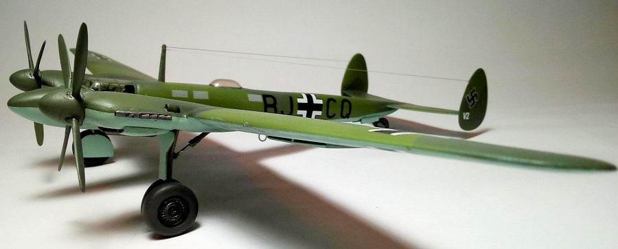
I decided to build the V2 (BJ+CQ) prototype, as it is the most documented and photographed among the three.
I first marked the borders of the nicely formed vac styrene parts with a marker, then cut them with scissors outside the border. All those parts were lightly pressed and rubbed on a 220 grit sandpaper, layed flat on a suitable surface. This sanding went to the point that it reached the marker traces. After this initial sanding down, I started to glue subassemblies: the front and rear wing halves, the fins and the two fuselage parts. If you take your time and do frequent test fitting and the inevitable microtrimming, you will end up with well-fitting subassemblies.
The styrene quality is super: easy to work and reacting well to styrene
glue. Just take care and use the absolute minimu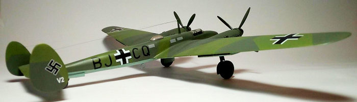 m amount of glue you need, as
any excess glue will run over the thin sheet styrene and create various and
potentially disastrous sink marks, with some of them very difficult to amend (as
was my case).
m amount of glue you need, as
any excess glue will run over the thin sheet styrene and create various and
potentially disastrous sink marks, with some of them very difficult to amend (as
was my case).
After initial sanding/smoothing, I glued the subassemblies together and the distinctive shape of the Adolfine emerged. Some misalignments occured, most (if not all) of them due to my vac inexperience. It is very crucial to have good alignment of the parts in a vac kit, as any attempts of smoothsanding the misaligned areas will almost always result in walls thinning to the point of structural weakness or failure (breakage of parts, streaks, holes) that are extremely difficult to fix. Corrective actions included reinforcing the affected areas with styrene rods or fillets, and try to smooth everything upon drying.
Needless to say I had a lot of such mishaps, with the highlight of the show being the twice breakage of the plane in two parts aft of the main wing. Upon second breakage, I was seriously thinking to toss it. However, my nature of giving another chance, plus the lessons that would be learned, resulted in my persistence to go along......Fixing was a pain and was done as described above: rods, fillets, tons patience and praying finally did the job (6 footer at best!).
Upon finishing of that vicious circle of breaking and fixing, I moved on and glued the 4 vac supplied under-cowling engine air inlets and 4 smaller top ones that were not suplied and were fabricated from 1/72 leftover Sidewinders, drilled accordingly for a more realistic view.
With the basic shape brought together, I proceeded to cut the positively marked cockpit and wheel well openings. Patience and precision cutting are of utmost importance here. Do a gradual precise cutting and you will be rewarded.
The cockpit area is of course an empty hole. A lot will be seen under
the very clear vacanopy, so some detailing was done. First, a floor, made of
leftover sheet styrene was installed. After viewing some pics, I
 saw a
“half” cockpit rearwall behind the seats. This was done with sheet styrene as
well. I used the nice resin kit seats and instrument panel. Side consoles with
generic detail were added, made of block styrene. Only one resin control column
was offered, so I used two 1/72 B-17 leftovers.
saw a
“half” cockpit rearwall behind the seats. This was done with sheet styrene as
well. I used the nice resin kit seats and instrument panel. Side consoles with
generic detail were added, made of block styrene. Only one resin control column
was offered, so I used two 1/72 B-17 leftovers.
RLM02 (Hu31) was used for general cockpit painting, with black instrument panel, control wheels and side consoles. Some silver drybrushing and seat belts made of masking tape finished the task of making this 1/72 cockpit look busy enough.
Those wheel well openings are also totally empty, so their floors and some walls were fabricated from sheet styrene. I superglued a piece of grid looking mesh in each main wheel well floor, to add more interest and weaken the feeling of emptiness. I glued the scissors at each main landing gear leg. Retraction cylinders are not provided, so the leftover bits paradise contributed again. Landing gear bays, legs and doors inner faces, were painted RLM02. The oleos were highlighted with my PILOT extrafine silver pen.
The main resin wheels are works of art. Together with the rear wheel, their rims were painted black (drybrushed with silver), and the tyres “mouse grey” (Hu92).
The under wing flat air inlets are not provided. Those inlets were fabricated from sheet styrene (for the flat part) and stretched sprue (for the minuscule height side walls). Their position and dimensions were figured out from the kit supplied 3 view plan and net found schematics.
The landing gear doors were fabricated from the kit's leftover sheet styrene, their shape and dimensions based on drawings and wheel wells measurements. The ones that are attached to the MLG are curved, and I replicated them by simply hand-bending them to shape as per reference pics
I then turned my attention to the really beautiful resin exhausts. They were cleaned and painted Testors Burned Metal. Of course, I managed to break one, but thick super glue did its remedial action. Since no exhausts for the internal cylinder block are provided, after studying 3 view plans, I fabricated two, made of side-cut qtip chunks. They were painted Burned Metal as well, looking believable indeed!
At this time I decided to cut the clear vacs to shape, in order to see if they would fit adequately enough. Regarding the canopy, fit left a lot to be desired, something I was expecting. Microtrimmings of the cockpit opening and the canopy, resulted in an acceptable fit, to be smoothed with white glue as a filler at later stages. The astrodome fit well on top of the fuselage. No cutting was done there, with the underlying area painted flat black to resemble the opening.
So, with confidence building up, I sanded the plane with 1500 grit and headed to the paint shop!
| COLORS & MARKINGS |
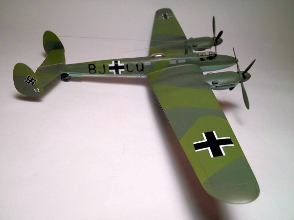
The camo scheme is the classic RLM 70/71 over 65. For this, I first sprayed the undersides with Hu65 and masked them with masking tape. The landing gear doors outsides were painted the same shade, too. Then the topsides were painted with a custom made RLM70 dark green shade, using Hu78 as a base, darkened with Hu33 black to look “right”. The props were painted RLM70 as well.
 After masking the dark green areas, I sprayed Revell 360 (darkened a
bit) for the RLM71. Upon unmasking, I did whatever touchup required and gave the
model a coat of Future to prepare the surfaces for the decals. As decals were
generic, I used spares from my decal dungeon.
After masking the dark green areas, I sprayed Revell 360 (darkened a
bit) for the RLM71. Upon unmasking, I did whatever touchup required and gave the
model a coat of Future to prepare the surfaces for the decals. As decals were
generic, I used spares from my decal dungeon.
There are some intricate side fuselage crew windows. Those were depicted with leftover silvergrey decal suitably cut pieces.
Weathering was on the subtle side, since those prototype Adolfines were practically used under “evaluation” status, making me concluding that they were kept in “good” condition. This can be justified from existing photo reference. So, using mostly pastel chalks and some dark washes, I applied some light weathering on topsides, and some more heavy (engine stains, hydraulic leaks, tire dirt etc) at the undersides.After performing whatever micro touch-up I could spot, a final coat of future sealed everything in.
The already clear canopy was dipped in future for extra clarity, then hand painted RLM70.
| FINAL CONSTRUCTION |
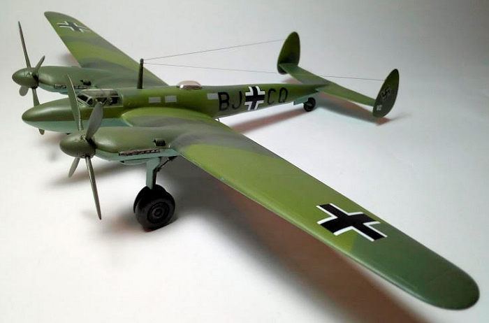 I superglued the landing gear in position and, after curing, I
superglued the wheels.The main wheels holes are way too large, but If you take
your (quality) time here and use the thickest superglue you have, you'll end
with a nicely aligned landing gear. The LG doors were glued in position too, as
were the propellers, which are keyed, rotating inwards, after giving them a
subtle silver drybrush.
I superglued the landing gear in position and, after curing, I
superglued the wheels.The main wheels holes are way too large, but If you take
your (quality) time here and use the thickest superglue you have, you'll end
with a nicely aligned landing gear. The LG doors were glued in position too, as
were the propellers, which are keyed, rotating inwards, after giving them a
subtle silver drybrush.
A loop antenna was fabricated from stretched sprue, painted RLM65 and attached to the undersides, as per net drawings. The antenna wires were made from silver molded stretched sprue. The nice resin top double antenna mast was replaced with a same looking scratchbuilt styrene one, as I find it easier to glue stretched sprue to styrene than resin. It was painted as the surrounding RLM70.
After any required touch-ups performed, the model was given a coat of satin varnish (mix of Humbrol 70% gloss and 30% matt). I tried to spray it unevenly, for a more realistic look.
Upon drying, I attached the clear parts with white glue, which doubled as an excellent filler for the remaining gaps.
I then called my Adolfine done!
| CONCLUSIONS |
This was an enjoyable model to build. Being it my first vac, I made a lot of mistakes, which I hope not to repeat with my second one (yes, more will follow!).
As a vac, with many resin detail parts and quite a few scratchbuilt work required, it is not a model for an abslolute beginner, but more for a modeler with a few short run multimedia kits under his belt.
This Airmodel kit itself is very nice, with beautiful vac and resin parts. Omissions, as stated above, do exist, the most important ones being the underwing oil coolers and the inner cylinder rows exhausts, but all omissions can be scratchbuilt with good degrees of success. Moreover, it is to my understanding that Airmodel might account for them in their future re-releases.
A full resin kit of the Adolfine, with white metal LG parts and vac clear parts, made by Planet Models, is also available. This looks truly amazing, full of great detail, and is definitely the better kit. However, it comes for a price at the region of 70 Euros. Compared with the really low price of the Airmodel (only 18.5 Euros), the choice decision among the two becimes an interesting procedure....
I've got both of them, which is a nice decision too!
If you have some of the above mentioned building experience, do yourself a favour and go build a vac. Make your mistakes and don't be hard to yourselves. Keep walking and finish it. This fantastic feeling of achievement will last forever in your modelling soul, trust me.
Happy modelling!
| REFERENCES |
Wikipedia (for the historical section)
The net (for pics, drawings and any other info)
25 January 2021
Copyright ModelingMadness.com. All rights reserved.
If you would like your product reviewed fairly and quickly, please contact the editor or see other details in the Note to Contributors.