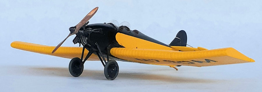
SMER 1/48 NB-3
| KIT #: | 0819 |
| PRICE: | $15.00 |
| DECALS: | |
| REVIEWER: | John Summerford |
| NOTES: | EZ Mask stencils. Conversion of BH-11 kit |

| HISTORY |
“The Barling NB-3 was designed by Walter Barling in 1927. The aircraft was advertised as being able to right itself from any position with hands off the controls and also as being spin-proof. The NB-3 is a low wing tandem-seat, open cockpit aircraft with conventional landing gear. The fuselage was constructed of welded chrome-moly steel tubing with aircraft fabric covering. The wings used a unique double layered corrugated aluminum skin with a smooth exterior that required custom presses to handle the various thicknesses of material along the span. The center section was straight with dihedral in the outer bays. The spar was also aluminum with a U-shaped profile. The aircraft was powered by an Anzani 3-cylinder radial engine, Superior radial or LeBlond 60-5-D. The main gear used long struts attached to the upper fuselage for the largest landing gear geometry.
“The NB-3 was test flown by Claude Sterling in February 1929. The plane competed in the 1929 National Air Races, placing first or second in events in its class. The Marshall Flying School advertised the NB-3 as a one-day-to-learn-to-fly aircraft with students flying in the morning, an aerodynamics class, learning how to weld by mid-afternoon, salesmanship, and a leisure round of boxing and swimming by evening. Ruth Alexander established a new world record for altitude in 1930 using an NB-3 over San Diego, California. A NB-3 is on display at the N-B plant's hometown airport in Marshall, Missouri.
Ruth Alexander
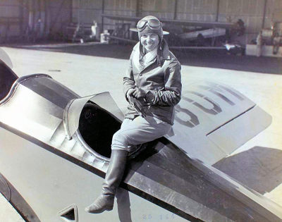
“On July 4, 1930, Ruth Alexander flew a Nicholas-Beazley NB-3 (Barling NB-3) light aircraft (serial number 52, U.S. Department of Commerce registration number 880M) to 21,000 feet; this was not confirmed as an official record owing to problems with the official barograph. Her altitude had exceeded the rating for the barograph drum. On July 11, 1930, Alexander took off at 1:34 p.m. in the same Barling from Lindbergh Field. After briefly losing consciousness at extreme altitudes despite using an oxygen tube, she established a new world record in light planes (for both men and women) of 26,600 feet at the apex of the flight. Later in July, Ruth became the first woman in the US to become an air deputy.
“In July of 1930, Ruth proposed to fly from Mexico to Canada via the U.S. – a “three flags flight” along the west coast air route. Tex Rankin had established a speed record over this route and Ruth wished to exceed it. In addition, Ruth looked to become the first woman to make a round trip flight from Canada to Mexico, and the first woman to fly from Canada to Mexico non-stop. Her northbound route started on August 27, 1930 from Agua Caliente, Tijuana, Mexico to San Diego and then Los Angeles. On August 28 she continued from Los Angeles to Oakland, then Portland. And on August 29, she completed the northbound leg to Seattle before finally landing at Vancouver (Lulu Island).
 “The return
leg on August 31 started at roughly 3:20 a.m. from Vancouver and concluded back
at Agua Caliente at 7:15 p.m. for a total flight time of 15 hours, 54 minutes,
30 seconds. The 1,460-mile journey was flown at an average speed of 91.25 mph
which was the fastest time by a woman on the route but not faster than Rankin’s
prior 14 hours and 37 minutes. The flight earned NAA records for distance over a
specified air route by a woman, and a speed record over the course by a woman.”
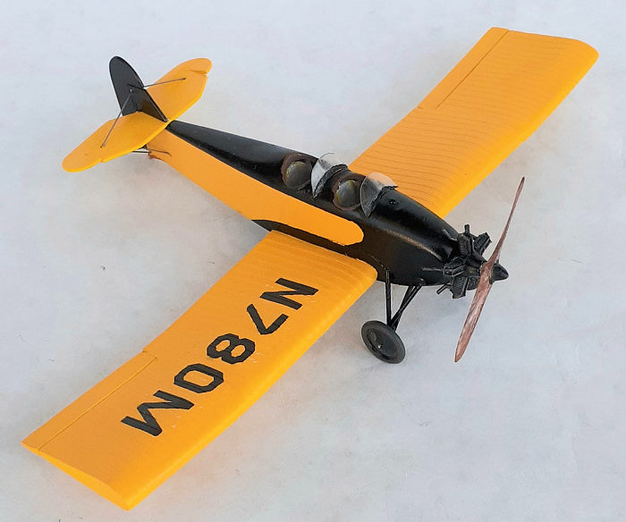
I built this model of aviatrix Alexander’s altitude record flight on behalf of the Northwest Scale Modelers. The group has a close relationship with the Museum of Flight, located at the southwest corner of Boeing Field in Seattle, WA. (If you are anywhere near the Puget Sound area, I strongly encourage you to take a day--yes, an entire day—to visit.) One of the club’s activities is to display models centered around aviation themes in a pair of display cases located off the lobby of the main building at the entrance to the Wings Café. The theme of this particular display is “Woman of Aviation”. Typically, the themes are changed every three months.
Being as the fuselage geometry, wing size plus planform, (just a couple of centimeters difference in length and span between the airframes) and five-cylinder engine are similar, the Avia BH-11 serves as a good starting point to create a model of the NB-3.
| THE KIT |
 Inside an
end opening box is a single bag of holding two sprues of light gray-green
plastic holding 34 parts, including a pilot figure. A small bag has the
windshields. The only cockpit details are a pair of blank instrument panels and
a pair of seats. Ejector pin marks mar the sidewalls. Wing rib and tail surface
detail is raised.
A 41/2-inch by 5-inch sheet has 20 decals that appear dense. Two styles of Check national markings and four sets of squadron badges make up the content of the sheet. The instructions show where to apply the set of national roundels on a single-color scheme while the bottom of the box shows a three-color camo scheme for the other set of markings.
Four pages of a single-fold sheet comprise the instructions. The first page has history and data in Check and English. Page two has German history and data and general building instructions in Check. The third page is pictograms of eight assembly steps. The final page is a painting and decaling guide with colors called out in the Humbrol range.
| CONSTRUCTION |
With scant data and a handful of mostly grainy photos, I examined the kit parts to determine a plan for this “forensic” build. The nose of NB-3 is more tapered than BH-11. The tail surfaces are larger and shaped entirely different. The kit wings are far more complicated in camber across the span. They are thickest at the strut attachment points and taper towards the tips and fuselage versus the constant cord and camber of the NB-3. They’re also attached to the fuselage slightly more forward than NB-3.
I started by reinforcing the interior of the nose with drops of super glue to enable a more tapered appearance. The irrelevant holes were filled in and sanded. I decided to scratch build the wings, (sigh) so I drilled holes to accept a spar and align the wings. I also cut out a triangular foot hold on the left side.
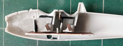 For the
interior, the instrument panels painted with a wood effect and the rear panel
decaled with instruments from the decal dungeon. (The front panel was just a
bulkhead. That compartment was for a passenger or cargo.) Scrap styrene was used
to create a floor and also given the wood treatment. A pair of rudder pedals
made from strip stock and rod stock for the control stick finished that
subassembly. Bits of 3/64” rod were cut to length and glued to the sides to
represent frame structure. The seats were given some lap belts made from card
stock.
After gluing the fuselage halves together and addressing the seam, some card stock was taped to the rear end to sandwich the tail strut, thus preventing any damage. I set about re-shaping the nose into a tapered appearance. I also elongated the engine mounting hole upward to center the engine in the cone of the taper. The headrest/pylon was cut down and also re-shaped.
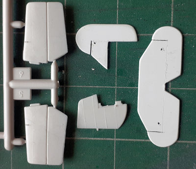 Moving
on to the tail, I used the kit parts as references to size of the pieces and did
my best to determine the shape. I broke out my old school drafting tools and
drew out the shapes on .030 sheet. After a rough cut, files and sandpaper were
used to get the final result. I cut the horizontal gap between the fin and
rudder plus the gaps running fore and aft between the stabilizer and elevator.
Holes were drilled for the bracing wires. I scribed the hinge lines and bent a
droop into the elevator.
Before attaching anything to the fuselage, scrap paper and an oval template was used to create templates for the windshields. These were glued to tape and that piece was pressed onto a piece of .015 clear butyrate sheet. That was set aside for later.
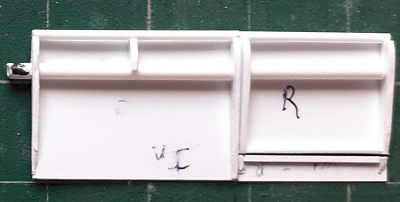 Now it
was time for the wings. Two rectangles, each an inner and outer wing underside,
were cut out of .020 styrene and taped down together on the work mat. A spar of
5/32nd tube was glued across the
sheets and then cut at the break to separate the panels.
Ribs made from .060 sheet styrene were cut out and glued to the ends of the panels. The ribs at the breaks were tilted two degrees to create a four-degree dihedral. A single nose rib was glued in the middle of each inner wing. A 3/32” tube was glued to the front of the ribs to act as the leading edge of the wings. Upper wing surfaces were cut oversized from .010 sheet. Each panel was placed vertically on the leading edge at the edge of the corresponding top sheet and liquid cement applied at the contact area and left overnight. The top panels were wrapped around the ribs, clamped and glued. Filling and sanding followed.
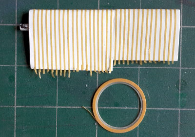 Fortunately,
the height of the corrugations is not as prominent as on a Junkers or TBD
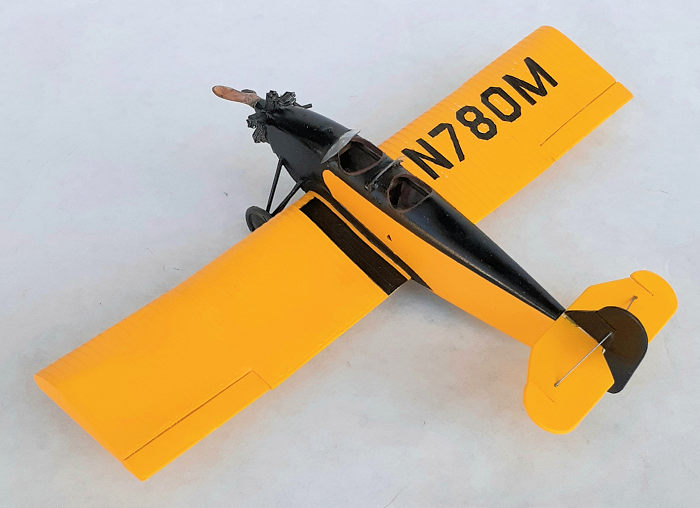
Devestator, so I simulated them with 1mm wide masking tape. A tedious 33 pieces
of tape laid down on the first wing in just over an hour, so that’s about two
minutes per corrugation. A five-meter roll was used up and another roll started
to complete the other wing. (Whew!) Using a fresh razor blade and a steel edge,
the tape was trimmed a millimeter inside the trailing edge. A polyurethane based
primmer thinned with lacquer was brushed over the tape to soften the edges and
seal the tape in place. A second, undiluted coat was applied.
When test fitting the wings, I discovered that I didn’t account for the taper of the fuselage and had an awkward gap to fill. I removed some material where the wings mated and used filler to make up the difference.
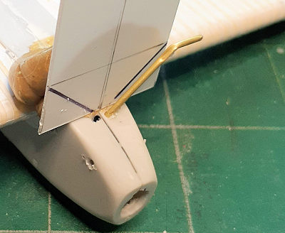 On the
sides of the NB-3, just above the wings are odd doublers, or perhaps they are
kick plates for entering and exiting the cockpits. I cut out a pair from .010
sheet styrene and glued them in place.
Locating holes for the landing gear struts were laid out and drilled for 1.1 mm brass tube. The angles for the inboard struts/axles were marked on some scrap sheet and held in place with a blob of Silly Putty. With that as a reference, the struts were glued in place. The other struts were cut to length and glued to the locating holes and axle. With that, the model was ready for paint.
| COLORS & MARKINGS |
The
paint scheme reminds me of a school bus. Two coats of yellow with a light
sanding in between were laid down. The regestration numbers on the wings were
created with masks from E-Z Masks. This was the first time I used them. I found
them a bit tricky to lay down, and they worked quite well. The rest of the model
was masked and the black sprayed on. Once all of the masking was removed, the
leather padding around
 the
cockpits was brushed on.
After painting, the tail surfaces were glued in place and their bracing wires attached as well as the rudder control cables.
Attention returned to the wind shields. They were cut to shape and a curve induced by working them around a dowel. A mounting frame was simulated with black paint that hid the bead of cyano gluing them to the fuselage. I did have to make a couple of touch-ups.
All that was left to do was add the wheels, engine, and prop and the model was complete.
| CONCLUSIONS |
I’ve never built a Smer kit before and held them in low regard. In this instance, I think you get a lot of bang for your buck. The Avia BH-11 is not a complex airframe, and neither is the kit. One can scratch build needed cockpit details, or purchase after-market parts and engine. Either way, since the parts fit well, the kit can be an enjoyable build.
Conducting on-line research for several hours and making this conversion was also enjoyable. Without benefit of drawings, I think I achieved a good representation of a NB-3. Where I to do it again, I’d use more structure in the wings and change some details that, of course, I noticed after I finished.
11 December 2020
Copyright ModelingMadness.com
If you would like your product reviewed fairly and fairly quickly, please contact the editor or see other details in the Note to Contributors.
Back to the Main Page Back to the Review Index Page Back to the Previews Index Page