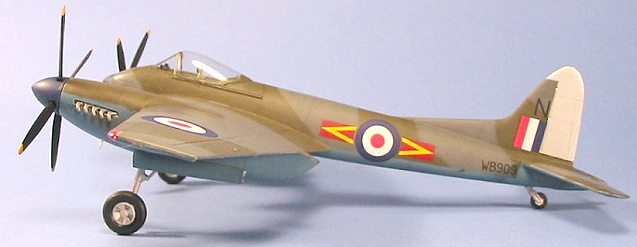
|
KIT # |
458 |
|
PRICE: |
$60.00 |
|
DECALS: |
Two aircraft: 33 and 64 Squadron |
|
REVIEWER: |
|
|
NOTES: |
Short run with resin. |

|
HISTORY |
The initial concept of the D.H.103 design was that of a scaled-down single seat version of the Mosquito, capable of meeting single engined Japanese fighters in long-range combat among the islands of the South Pacific. Rolls-Royce Ltd. developed special Merlin power plants of minimum frontal area for the aircraft, which permitted an exceptionally sleek installation. Permission to build was not received until June 1943 when the D.H. 103 ceased to be a private venture and Specification F.12/43 was written round it. At this time it was named "Hornet."
 The Hornet was an
entirely new design, sharing with the earlier Mosquito only the method used for
manufacturing the slim, oval section fuselage. The one piece. two spar,
cantilever laminar flow main-plane was designed to high strength factors and
consisted of a composite wood and metal internal structure with a stressed birch
ply double upper skin and an undersurface of reinforced Alclad. The Hornet was
the first aircraft in which wood was cemented to metal - a unique method of
construction only possible by using the revolutionary new Redux adhesive.
Piloted by Geoffrey de Havilland Jr., the first prototype - RR915 - flew for the first time on July 28, 1944, only 13 months after the commencement of detail design. Estimateed performance was met easily; maneuverability and climb were exceptional and the prototype reached 485 mph. With two 200 gallon drop tanks under the wings, the Hornet had a range of over 2,500 miles cruising at 340 m.p.h. at 30,000 ft.
Production of the Hornet F. Mk. 1 began at Hatfield late in 1944; the first aircraft, PX210, was delivered February 28, 1945 but the war with Japan was over before any Hornet-equipped unit reached IOC. The production Hornet was only marginally slower than the prototype, with a top speed of 472 mph at altitude and were capable of an astounding 400 mph at sea level.
 The Hornet F. Mk. 3
were equipped with wider horizontal stabilizers, larger elevator horn balances
and two 200 gallon under wing tanks - which could be removed for the carriage of
two 1,000 lb. bombs. Internal fuel capacity was increased from 360 to 540
gallons which gave the F.Mk.3 a 40% increase in range. The F. Mk. 3 was first
seen in public at Farnborough in June 1946; the type remained in production at
Hatfield until the jigs were moved to Chester late in 1948. The first
Chester-built Hornet flew in March 1949 and with completion of the last in June
1952, a total of 211 Hornets had been delivered to the R.A.F. The production F.
Mk. 3s was distinguishable from the F.Mk.1 by an extended dorsal fin, which was
later fitted to all Hornets to improve stability at high speeds.
64 Squadron - the first equipped with the Hornet - took part in the Victory Fly Past over London on June 8, 1946. 19 Squadron received Hornets at Church Fenton that October, with 41 and 65 Squadrons similarly equipped in following months. On May 20, 1948, 65 Squadron was chosen to fly to Uppsala to pay an official visit to the Swedish Air Force. On September 15, 1949 one of two Hornets which was to participate in Battle of Britain celebrations at Gibraltar was flown from Bovingdon to Gibraltar by F/Lt. H. Peebles at an average speed of 357.565 mph, which set a British point-to-point record. On the return journey September 19th, Group Captain A. C. P. Carver flew to Bovingdon under strict cruise control at an altitude of 25,000 feet in 2 hours, 30 minutes, 21 seconds, and landed with 15 minutes fuel, setting a new record of 435.871 mph.
 De Havilland test
pilot G.H. Pike came third in the High Speed Handicap Race at 343.5 mph in
F.Mk.1 PX224 at Lympne on August 31, 1946. PX386, a new F.Mk.3 powered by 2,030
h.p. Merlin 133/134 engines, took part in the National Air Races at Elmdon on
July 30, 1949. Flown by G. H. Pike in the Air League Challenge Cup, it came
second and made the fastest time of 353 mph. (Reading this, one can only think
what a sensation the Hornet would have been in the post-war Thompson Trophy
Races.)
The Hornet F.Mk.1 was declared obsolete in 1950. In 1951, almost all of Fighter Command's F.Mk.3s were sent to Malaya for use by the Far East Air Force, where they were equipped with under wing rails for eight rocket projectiles or racks for two 1,000 lb. bombs and used for highly successful attacks against jungle terrorists, flown by 33 and 45 Squadrons. They were the last piston engined R.A.F. fighters to see active service.
|
THE KIT |
For a review of what's in the box, see the preview.
|
CONSTRUCTION |
Construction starts with the cockpit, and will be the main focus of this review, inasmuch as this is the one area that will provide any difficulty in construction. To put it bluntly: if you get this wrong, you don't need to waste time with the rest of the kit.
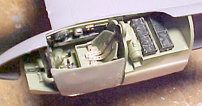 I mistakenly painted
my cockpit British Interior Green; it should rather be flat black. By the time
I realized this, I had also discovered the difficulties that accrue to not
getting things exactly right in this stage of construction, and had already
botched one of the two canopies. Being unwilling to risk damage to the only one
I had left, I decided this would be a model of the special Hornet F.Mk.3 that
left the factory in 1952 in an experimental British Interior Green finish to see
if the cockpit could be cooled at all in tropical conditions found in Malaya
with a cockpit that was not painted black.
The big thing you have to accomplish in this part of construction is to be sure the resin cockpit insert will fit inside the fuselage halves easily; if you have to apply the least amount of force to glue the halves together in the vicinity of the cockpit, you didn't get the fit right, and will pay heavily when you attempt to fit the cockpit canopy in place. When I do my next one, I will not only dremel down the main cockpit resin part, I will also dremel out the fuselage halves in the area of the cockpit, to insure an easy fit. Things very tight here, and you will benefit from frequent test-fitting before applying any glue to these parts.
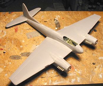 Other than all the dremeling for fit, the parts of the cockpit go together easily and provide ample
detail to look good under that big clear bubble canopy.
Once you have accomplished this and have the fuselage together, you have to deal with the one Really Difficult Problem of the project: the fact that the canopy is not correct. As molded, the lower rear of the canopy is not shaped correctly, and will not fit properly if you do not modify it. Cutting the outline shape of the canopy to the proper shape is easily done with fingernail scissors, though you will have to rescribe the canopy frame to get it right for painting. Given the clarity of the canopy, and the fact that having it open really destroys the beautiful lines of this airplane, I chose to attach the canopy in the closed position. (One hopes that Falcon will quickly make an accurate canopy.)
Those Who Know This Airplane Better Than I have pointed out that the way the nose is molded, you cannot accurately fit the windshield in place. I chose to trim off the extreme front of the windscreen to fit the opening. I have since learned that what I should have done - and will do on the next one - is to file down the coaming over the instrument panel, so that the windscreen as molded will fit over that coaming. The way I did it looks good, and I doubt many would notice it was wrong had I said nothing, but here is the trick to doing it right rather than just getting it done.
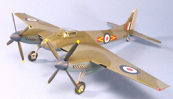
As regards the rest of the assembly, there are no problems in assembly, other than you must trim off about 1/16" from the crossbar of the retraction oleo in the landing gear so that the assembly will fit inside the wheel well.
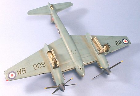
 Some people have
complained about the lack of detail inside the wheel well. From the research I
have available, it does not appear there really was all that much in there.
Once the model is assembled and is on the shelf, there's little to be seen. If,
however, you simply must have some detail there, I would suggest using some thin
Evergreen strip to make internal structure following the panel lines on the
outside of the engine nacelle. I also thinned down the inner walls of the gear
well opening, and the gear doors, which results in a much better fit of these
parts in the open position.
I assembled the wings without making any spars, butt-joining wings to fuselage the way the kit was designed, with no problem. If you want to put in a spar, I would do two - one to fit into the wing immediately aft of the assembled radiator, and one about an inch further to the rear.
The tail wheel as provided is completely inaccurate, since it should be an "anti-shimmy" wheel like that used on the Mosquito. I cut off a section of sprue tree the right diameter, glued it between the two wheel halves, then sanded them down a bit in diameter and also sanded the wheel to make it thin enough to fit in the tail wheel fork. This looks close enough, though I am aware there is an accurate tail wheel that will be included in the Cooper Details set for this kit.
|
CAMOUFLAGE & MARKINGS |
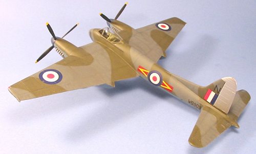
 Painting:
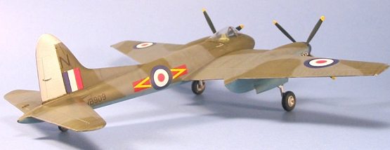
I pre-shaded the model, then painted it PRU Blue for the lower surface, mixing this color from both Gunze-Sangyo and Tamiya paints. The upper surfaces were painted with Dark Ocean Grey from Tamiya and British Dark Green from Gunze-Sangyo. Since these airplanes were camouflaged "in the field" (the original scheme being either overall silver or PRU Blue lower surfaces and Sea Grey Medium upper surfaces), I freehanded the scheme. When all was dry, I gave the model a coat of Future.
Decals:
The kit decals are printed by MicroScale and went down with no problems under a coat of Micro-Sol.
|
FINAL CONSTRUCTION |
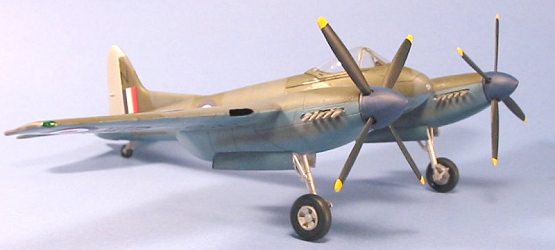
I had painted the prop spinners with Tamiya "Flat Blue," The props were attached, being careful to insure that the right prop went on the right engine - they rotate inward. The landing gear and gear doors were attached. The kit wheels are really for the F.Mk.1, the heavier F.M.3 using a slightly-larger tire - again, the Cooper Details set will have this wheel.
|
CONCLUSIONS |
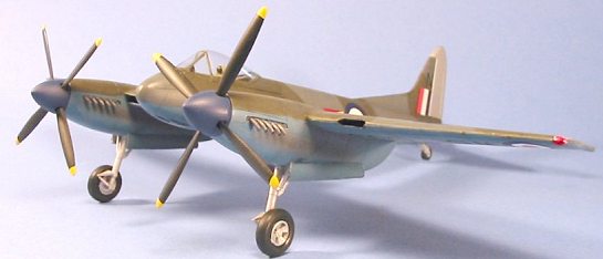 The kit builds up into
a convincing representation of the Hornet, and I like the model. However, at
nearly US$60.00 retail, I'd like to have seen MPM provide accurate wheels and
the 200-gallon drop tanks, and a photo-etch instrument panel would have been
better than the resin part provided. I plan on using under wing rockets from a
Hobbycraft Sea Fury to finish off the model later. It ticks me off to have to
say for those who want a really accurate model that they need to tack on another
$20-odd dollars for the Cooper Details set, but it will improve the look.
That said, this Hornet built strictly out of the box should satisfy most modelers. It looks great sitting on my shelf in the RAF collection.
|
REFERENCES |
Birtles, P.: "The de Havilland Hornet," Profile 174; Profile Publications, 1968.
(For a newer reference, Warpaint #19 is also a good source. Ed)
January 2003
If you would like your product reviewed fairly and fairly quickly, please contact the editor or see other details in the Note to Contributors.