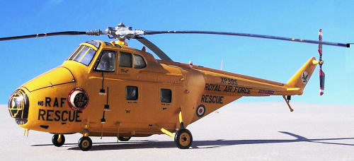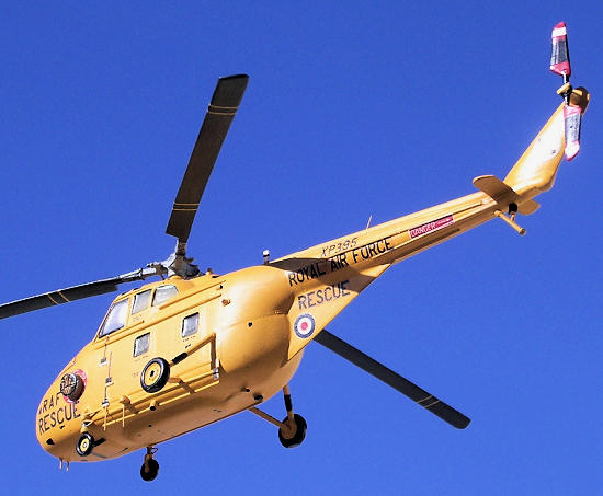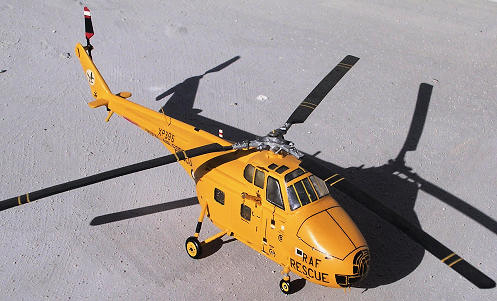
Airfix 1/72 Westland Whirlwind HAR.10
| KIT #: | ? |
| PRICE: | 2.5LM |
| DECALS: | One option |
| REVIEWER: | Carmel J. Attard |
| NOTES: | Converted with additional replacement nose. |

| HISTORY |
In 1950
 other nations. Initially the Royal
Navy received 25 x S-55 under the MOAP and this was followed by
production of the type to become the mainstay of the rotary wing element
of both the Royal Navy and the RAF in the original piston-engined form.
The Whirlwind
| THE KIT |

| CONSTRUCTION |
Starting with
a good set of reference scale plans from Aviation News series of
drawings one could note that the principal part of conversion to
The next stage was to prepare the fuselage from the Airfix kit in
order to take the new nose section. The fuselage halves were held
together with scotch tape and make a vertical cut across the nose
section and at the tail boom area. The nose was cut just ahead of the
windscreen and the tail boom was cut at an exact spot where there was a
pronounced downward ‘crank’. It was imperative to make frequent
reference to scale drawings when marking for cutting. The aft fuselage
was cut vertically from top of the tail boom, and then removing a tail
boom fillet and later rejoined the section from the cleaned-up edges,
which were faired smooth by a small amount of filler followed by
sanding. The kit dorsal spine was filed away and a new one made from
plastic card fitted instead. The rear of engine compartment
 was also
built up with filler, as the shape of the kit area was too flat. A
beacon light was fitted on this area. The tail boom stabilizer was also
enlarged by inserting a 1/8 inch narrow plastic strip, this was filled
with filler at the joint and then filed to shape. A new tail unit was
made from a thick scrap piece of plastic as this had a totally new shape
to the kit part. The main propeller blades were also built from plastic
card, as the kit prop was 1mm narrower. The blades once shaped were
glued to the central part No23. A new aft stabilizer replaced the kit
part No33, which was fitted in level position instead of an inverted Vee
shape. Tail rotor was scratch built from plastic card as the kit one was
short and narrow.
The assembly starts by assembling the cockpit floor and the rotor transmission of the Airfix kit. This was painted light gray and allowed to dry. The cockpit side windows were also enlarged as these appeared slightly under size when compared to scale plans. Instrument console, seats, crew figures etc were all painted and fitted in place. The fuselage halves were closed and cemented. A firewall made of 1mm plastic card was added to the front to close the cut open section and the prepared replacement nose was aligned and fitted to it using small amount of super glue. I thought of adding a couple of guiding plastic rods at the inside for more rigid strong joint but found it was not required and I was happy with the firm complete fuselage front. The seam was sealed with more talc powder and dope mix followed by smooth sanding. With the nose and tail boom in place the next stage was adding the three small aerials to the lower fuselage and three antennae added to the fuselage at different places, tail bumper from bent wire and shaped plastic pieces and the stabilizers were added from the kit supply. The hoist/winch was fitted to the starboard side of cabin. Adding two pillar brackets made from stretch sprue modified this attachment. A heavy round engine exhaust was cut and shaped from a ballpoint pen cover that matched the diameter and then cemented to the fuselage. The tail boom also had detail added to its side in form of four external strips attached longitudinally along the sides. Front screen windshield and forward side window were fixed in place and masked. The remaining window apertures were masked with the capillary action of Maskol so that when airbrushing the kit the interior is not affected. The assembled fuselage was given an overall coat of matt white to reveal any imperfections and also as a base in preparation for the overall yellow finish of the kit.
| COLORS & MARKINGS |

| CONCLUSIONS |
January 2010
If you would like your product reviewed fairly and quickly, please contact me or see other details in the Note to Contributors.