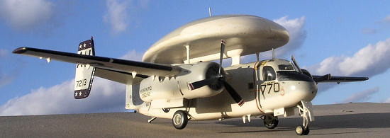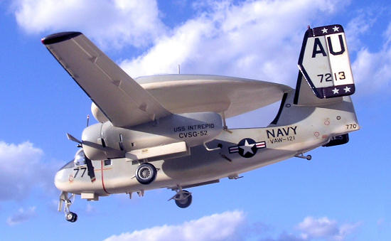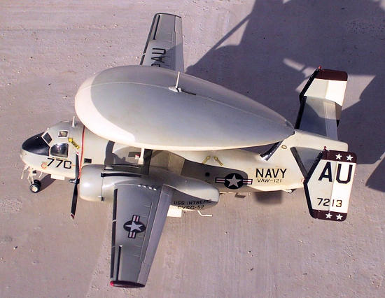
Hasegawa 1/72 E-1A Tracer (conversion)
| KIT #: | ? |
| PRICE: | $ |
| DECALS: | ? |
| REVIEWER: | Carmel J. Attard |
| NOTES: | Considreable scratchbuilding required. |

| HISTORY |
In the first case, Grumman developed the TF-1
Trader from the S-2 Tracker as a small transport for Carrier On-board Delivery
of personnel and supplies. This differed basically in having a new fuselage to
accommodate up to nine passengers or 3,500 lbs of freight. The designation was
changed to C-1A. A further variant of the same basic airframe is the E-1B
(Originally WF-2) Tracer, an
 airborne early warning station.
This
is basically a C-1A with APS-82 surveillance radar in a tortoise shell shaped
radome above the fuselage, necessitating a three-fin tail unit.
The Tracer differed from the S-2A design in having
the twin fin and rudder arrangement to counterbalance the large radome, and a
deepened fuselage just like the Trader with the same 18 inch extension of the
forward fuselage as featured on the later models of the Trackers. The Tracer
pioneered the ‘Airborne Command Post’ technique which it finally relinquished
some 15 years later to its successor, the purpose-designed E-2 Hawkeye.
An
aerodynamic test version of the Tracer flew for the first time on
| THE KIT |
| CONSTRUCTION |
It is
interesting how the Grumman Tracker design has led its way to the evolvement of
the C-1A which had a deepened fuselage of a COD cargo plane and the E-1B Tracer,
the Early Warning aircraft. The Tracer carried an enormous radome in shape of a
 carapace permanently stuck to the upper fuselage making it look a totally
different design to the Tracker. The Tracer also differed from the Tracker
design in having a twin fin and rudder, arrangement suited for the large radome.
Apart from the Trader style deeper fuselage there is a 1’6” extension to the
forward fuselage.
This somewhat challenging conversion involved use
of the Hasegawa/ Revell Tracker kit. In doing so it would involve replacing the
sonobuoy bays, located at the rear of the engine nacelles with shaped fairings
made of pine. This also involves cutting the fuselage in half forward of the
wing and inserting a spacer exactly ¼” wide and deepening the bottom of the
fuselage from a pine insert and fair it to conform to rest of the lower fuselage
with filler. The radome itself is fashioned out of pine. In a nutshell this was
a conversion involving several stages and should be an interesting task for
experienced modellers using the most basic techniques. In the end this would
turn into a satisfactory model suited for those keen on
Navy
6th and 7th
Fleet aircraft aircraft.
Fuselage and cockpit area are assembled as per
instructions and allowed to dry thoroughly, the fuselage was cut across at a
point at the front of wing rear location and a spacer inserted so that the
fuselage is increased by ¼”. The insert could equally be balsa or pine but as I
had a spare Tracker fuselage since I built the Trader, (Falcon kit conversion),
I cut the spacer from the spare redundant
fuselage.
The
next step was to modify the weapons bay area of the fuselage by building it up
to a more rounded and fatter shape of the Tracer. This was achieved by fitting a
piece of shaped pine underneath as mentioned earlier. The aft section of the
fuselage was also different shape from the Tracker. This was made using a shaped
piece of pine, joined to the rest of fuselage and the assembly was set aside to
allow to dry well.
The
next step was modifying the engine nacelles, where the rear section behind the
wheel well was removed. This was first marked with a narrow strip of tape across
and cut with an X-acto saw blade. A block of pine was glued to each nacelle to
form the new shape of rear nacelle extension. Again these were allowed to set
and dry and given the final shape with the aid of files and sanding. The next
step was to carve the radome out of pine. Incidentally yellow pine is ideal for
this purpose as it is soft and ea sy to work with, free from knots and does not
distort. I made cardboard templates to check the cross sections of the radome
while it was being shaped. Reference was made to scale plans in Aviation News
Vol.1. No 16. When the final shape was achieved I applied coats of sanding
sealer to bring radome into a smooth sheen finish. Any imperfections were
attended to using a mix of talc powder and dope to the right consistency. Smooth
sanding brought the final shape and finish. It was the turn of the Tracer
shallow central rear fin which was also shaped out of pine and glued in place
utilising a spigot that was formed to slot in. The area around the wooden tail
was faired with more filler.
The cabin windows were drilled and filed to shape with needle file. The engine and wings were assembled as per kit instructions and gaps above and at rear of engine nacelle to wing joints were filled and sanded smooth as more sanding sealer was added to rear pine section. The fins were cut and shaped from thick plastic card reclaimed from surplus back plastic of vac form kits I made. Two twin fins were made and sanded to the correct taper. The tail planes were also made out of plastic card and panel lines were carefully scraped with a blunt blade. Tail planes and fins were put together to take correct dihedral and slid into the central fin from the rear of a cut slot. The open rear of the slot was then filled up with correct amount of filer. The detail structure under the Radome was also made out of pine, shaped sprue, and a plastic shaped web. Metal pins inserted to strengthen the assembly when put together and fixed firmly to the radome and upper fuselage. The radome should have sufficient play in it to be able to adjust it slightly if need be to ensure that it is in the correct position and exact angle when viewed from the side.
| COLORS & MARKINGS |
 The
complete assembly had the cockpit area masked and was given an overall coat of
matt white as a base colour. This was then followed by the standard US Navy
colour scheme of semi matt insignia white and gull grey FS 36440. The leading
edge de icing boots and nose anti glare panel painted in Humbrol matt black.
Yellow masking tape strips were used to obtain perfectly straight line edges.
All lettering and
| CONCLUSIONS |
In a way this was an ambitious project that I built some time before I got hold of the Falcon conversion kit of the Tracer which appears to involve less work for sure. And there was so much fun going step by step. Out of two Tracker kits I was able to build a Tracer and later a Trader using the ‘Falcon’ Trader fuselage conversion.
January 2009
Copyright ModelingMadness.com. All rights reserved.
If you would like your product reviewed fairly and quickly, please contact the editor or see other details in the Note to Contributors.
Back to the Review Index Page 2021