Entex
1/72 DeHavilland No. 1 Biplane
| KIT #: | 8448 |
| PRICE: | $ |
| DECALS: | None required |
| REVIEWER: | Brian Baker |
| NOTES: |
First issued in the late sixties, sometimes seen at swap meets. |

| HISTORY |
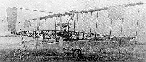
Geoffrey
DeHavilland’s first attempt at
building an airplane came in May, 1909, when he built his No. 1 Biplane in a
rented workshop from rough design sketches.
Mrs. DeHavilland did the fabric work, and F.T. Hearle helped with the
design and construction. In May,
1909, the semi-completed airplane was carried by truck (lorry) to Seven Barrows,
near Newbury, Berks, where an additional six months were consumed in final
adjustments before flight tests could be conducted.
The plane had a wing span of 36 ft., a length of
29 ft, and a gross weight of
850 lb., easily fitting into the current American Light Sport category. It was
powered by a 45 hp. DeHavilland Iris four cylinder water cooled engine driving
two opposite rotating metal props by means
 of a chain drive mechanism. The
landing gear consisted of four bicycle wheels, two amidships, and one at either
end. There were two
horizontal surfaces, a fixed one at the rear, and a moveable unit in front.
A small rudder was above the rear airfoil, and lateral control was
achieved by small ailerons on the wingtips.
The
plane’s career was very short lived.
In December, 1909, the first flight attempt met with disaster. To start
with, DeHavilland had never flown an airplane before, and this was his undoing.
He took off , but after becoming
airborne, he overcorrected on the elevator control, imposing excessive stress on
the wing structure. The wing failed,
and the plane crashed to the ground from a lofty altitude of fifteen feet.
DeHavilland was uninjured, but the plane was a total write-off. However,
the engine was salvaged for future use. Not an auspicious start, but DeHavilland
made up for it with his future creations, including the DH-4, Mosquito, Vampire,
and Comet, not to mention my favorite, the Tiger Moth.

| THE KIT |
The
instructions are printed on a large sheet, consisting of three 8 ˝ by 11 inch
sheets, covering all three aircraft.
In this case, the Entex kit, No. 8448, includes the Voison, (Voisin?),
Antoinette, and Dehavilland No.1.
All of the parts are listed by number and f unction, while a strip drawing shows
the assembly steps in recommended order.
There are no decals, and the only painting required is on the wooden and
metal components, such as the major fuselage structures, engines, wheels, and
propellers.
| CONSTRUCTION |
I trimmed
all of the components, and immediately applied the ‘Aeroskin” fabric to the wing
panels, elevators, and rudder. The
fuselage assembly came next, with a couple of small rectangular braces in the
forward part, giving it a measure of rigidity.
Next came the engine, which consisted of a small cylindrical shape with trunnions similar tothose on an old cannon.
The engine mounts on two small “engine stands” which are glued to the
lower fuselage longeron. The
location of the engine is not too clear
 in the instructions, and this is
critical because the engine has to line up with the chain drives, which are
mounted to the rear, and which connect to a pair of struts which are attached to
the rear spars of the lower wings.
The problem is that the instructions say to mount the lower wing to the
fuselage, but the instructions imply that both spars are to be attached to the
lower fuselage. This creates a much
lower almost zero angle of incidence, whereas the actual wing has a fairly high
angle, and the rear spar has to hang free to achieve the proper angle.
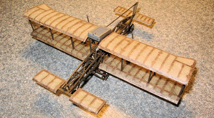
I ended up building up the biplane
wing structure and then attaching the whole thing to the fuselage, lining things
up with the prop mounting struts. I
had to enlarge all of the strut mounting holes with a drill, taking care not to
drill through the other side of the wings.
The struts can be attached with Tenax or any liquid solvent.
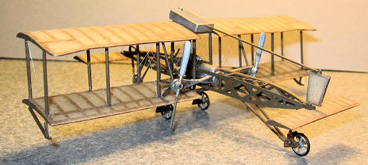
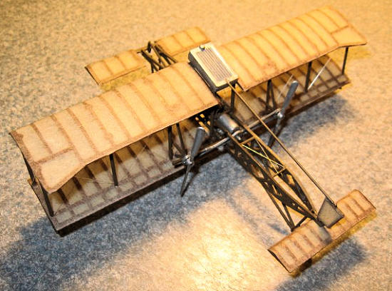
Once the wing structure was attached, and the chain drive was lined up
properly, I attached the forward elevator and tailplanes. The landing gear and
wheels were tedious to install, but when this was accomplished, the model was
ready to sit on its wheels. The
props went on last, and these merely were glued to the crankshafts.
No spinning props on this baby.
I added a seat belt to the seat, and the model was ready to rig.
| FINAL CONSTRUCTION |

| CONCLUSIONS |
February 2012
Thanks to If you would like your product reviewed fairly and fairly quickly, please contact the editor or see other details in the Note to Contributors.