When G. de Haviland left the Royal Aircraft Factory in 1914 to join
the Aircraft Manufacturing Company as chief designer he had been working
on the FE 1 and BE 2 designs. His first design for his new employer was
a two seat tractor biplane, but the War Office wanted a pusher design
similar to the FE 2.
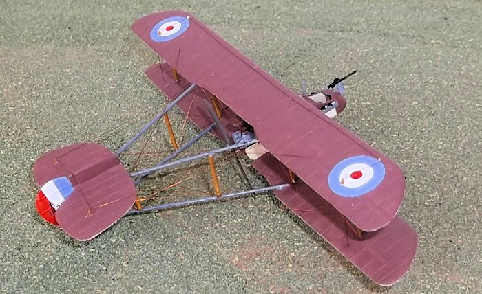 Consequently de Haviland produced a prototype
powered by the 70 hp Renault V8 engine. This first flew in January 1915
and an order for 49 machines followed. Called the DH 1 this machine took
a long time to get into production like all other British aircraft at
this time and as a result it was not widely adopted by the RFC because
the FE 2b had already been ordered in large numbers and had a better
overall performance.
The DH 1A was an attempt to improve the performance of the original
design by installing a 120 hp Beardmore
engine, (the same as powered the FE 2b), with a radiator behind the
pilot and a gravity tank under the port upper wing. It was armed with a
single Lewis machine gun on a mounting in front of the observer, and one
behind: the observer sat in the front cockpit. About 23 machines were
built and delivered to the RFC of which 6 were sent to Palestine to no
14 Sqdn who operated it alongside other types. It was used mainly for
escort duties but at least one enemy aircraft was shot down - a Rumpler
two-seater. The remainder of the DH 1 and 1A's were sent to home defence
squadrons in Britain or to training squadrons where the survivors were
finally withdrawn from service in the autumn of 1918.
There are kits of the DH1A available as vacuforms, but these are rare
and I have no experience of them. Others have described how to convert
an Airfix DH4 into a DH 1Aa conversion I had originally intended to do
over 30 years ago and even had a block of balsa with the side profile of
the fuselage nacelle marked on it
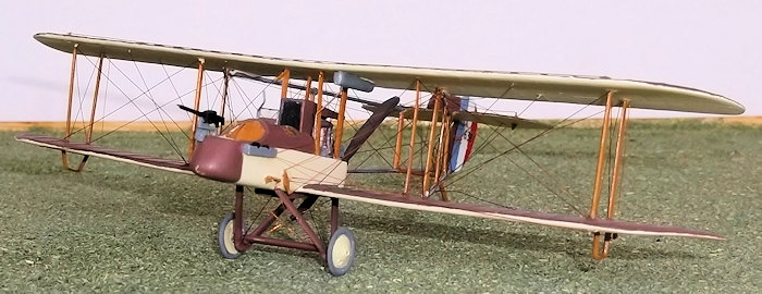 ready to carve, but then I gave up modelling! Since then the Datafile No 148 has been published and at last
reasonably accurate drawings of this machine have become readily
available in 1/72 scale. Having finished the Vickers Gunbus conversions
from the Airfix DH 4 (see previous articles), I thought that it was time
that I attempted this long postponed project and added this little known
pusher design to my collection. I was able to make use of the Datafile
and I would advise readers to do so if they wish to convert one of these
models as there is much useful information, good photos and accurate
drawings. If you want to build either the DH1 or 1A you will need a new
engine - a Renault in the case of the DH1 or a 120 hp Beardmore for the
DH 1A. I do not know of a source for a Renault engine but I was able to
acquire an Aeroclub Beardmore, although these are becoming hard to
obtain. You could of course scratch build either engine, (as I did with
the Beardmore for the FE2b - see previous article), as the drawings in
the Datafile would be a good starting point for the Renault and would
probably provide enough information for most modellers. For either
aircraft you will need a DH 4: I started with the Airfix kit as it was
inexpensive and reasonably accurate. I used the wings, struts, wheels,
axle and machine gun from the kit and a propellor from the Airfix Avro
504 which I happened to have in the spares box, but you could easily
modify the propellor from the DH 4.
I started by carving a male mould from balsa and cut out a female
mould from 5 ply wood. I used 30 thou plastic card to make the two
fuselage halves as already described elsewhere and then cut out the
pilot's and observer's cockpits and the rear top for the engine
compartment and radiator. Cockpit detail wa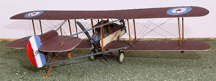 s basic - a floor, seats,
control column and rudder bar, some stringers on the sides and bulkheads
between the cockpits and behind the pilot's seat. The interior sides
were painted in clear doped linen, the floor, bulkheads and curved upper
parts of the fuselage wood, and the nose in aluminium. When you are
happy with the interior details cement the two fuselage halves together
and fill and rub down the joints: do not worry too much about under the
engine compartment as most of this will be removed later.
Cut out a small hole for the window between the pilot and
observer cockpits on the top of the fuselage and fill it with a
small piece of thin acetate: I used a piece from an old bubble
package. Now carefully remove the bottom of the rear fuselage
beneath the engine compartment, leaving two bars, one at the
rear of the underside of the fuselage and one at the top of the
rear of the fuselage on which the engine will rest later. I
painted the interior of the engine compartment clear doped linen
as the sides were fabric over a wood frame. I constructed a
radiator from card and scored the front with a sharp knife. The
sides and top of the cowling were from 15 thou card, as was the
engine cover, I rounded the edges with a file and worn fine
glass paper. I put two small supports for the engine into the
engine compartment and then started the fiddle to get the engine
to fit properly. Remember that the front of the engine sits
behind the radiator housing and the rear extends slightly over
the bar on the rear fuselage: I used a round file to shape the
groove in the bar. I also put a piece of card under the rear of
the engine to represent a fuel tank(?) - there is a feature
there as shown on one of the photos of the rear of a DH1A in the Datafile. When all of this was complete I cemented the radiator
into place followed by the engine, which had been painted of
course.
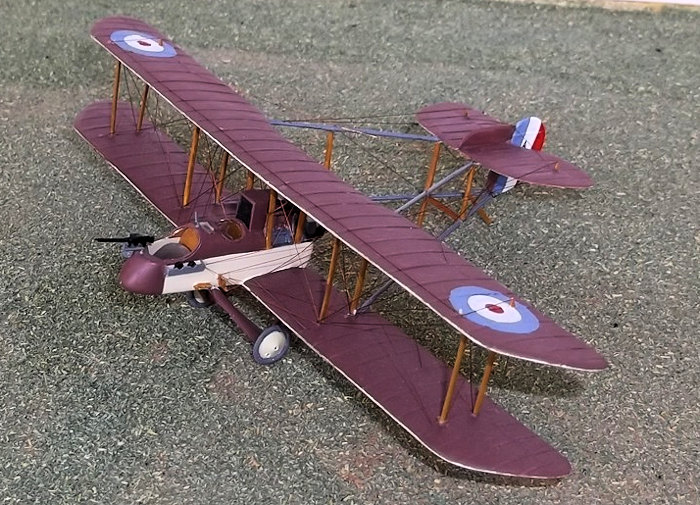
Final details can now be added to the nacelle. Drill two holes
for the front undercarriage legs, and make two ammunition boxes for
the observer from 10 thou card and cement to the nacelle sides. I
made a small air intake to fit on the starboard side just behind the
pilot's cockpit from 10 thou card and another intake underneath the
nacelle, also from 10 thou card. Coamings were added to the cockpits
from stretched sprue.
Start with the top wing by measuring the span of the DH 1. Mark
on the new tip shapes and cut off the old tips and file the new ones
to the correct shape. Now fill the grooves for the struts with the
arms which should be cut from the struts. When they are dry they can
be filled as can the holes for the fuel tank, the aileron grooves,
and any mould marks. When you rub down the filler also rub down the
ribs on the top of the wing. Add a strip of 2mm wide 20 thou card to
the rear of the centre section cut-out and fill the joint with
filler. When it is dry the cut-out needs to be extended sideways and
the card shaped so that the trailing edge is as thin as possible.
The wing tips also need to be shaped to a new aerofoil section. I
added new ribs by glueing strips of 5 thou plastic card to the wings
with liquid glue and when these were dry sanding them down until
they were nearly flat. This is a tedious and time consuming job and
I am not always certain that the result achieved is worthwhile. I
re-scribed the ailerons and marked the location of the new strut
holes before drilling them out. Straighten out the anhedral of the
wing by repeatedly gently flexing the wing between the fingers: the
light grey plastic is soft and flexible enough to do this if the
task is done gently. The new anhedral, which starts on the line of
the inner struts, can be bent back in the same way. A fuel tank was
made from two strips of scrap 40 thou card glued together, filed and
sanded to shape, and then glued to the underside of the port centre
section of the top wing. Drill a tiny hole near the front of the
tank for the fuel pipe.
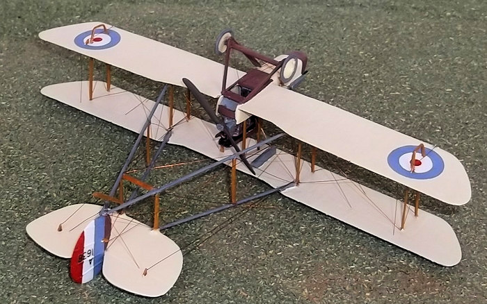
The lower wing of the DH 4 needs the centre section removing.
Lay the fuselage nacelle on the plan and butt one of the wings to
the fuselage so that the correct span can be marked on the wing tip.
Mark the new tip shape ensuring that the correct span is achieved
and then cut and reshape the new tip. Repeat this operation for the
other lower wing. Fill the strut holes, aileron grooves, moulding
dimples and remove the bomb racks. Rub down the wing ribs and filler
and then add two small pieces of 20 thou card to the cut out in the
centre section as per the upper wing. Reshape the cut-out to the new
larger size and sand the trailing edge of the card to a knife edge.
Add new ribs as described above and scribe in the new ailerons.
Finally re-align the anhedral as per the upper wing.
Lay the fuselage nacelle on the plan and check the attachment of
the wings: you may need to carefully shape the wing to fuselage
joint to get a good fit before cementing the wings to the fuselage.
Make sure that the leading edges of the wing are at right angles to
the fuselage sides and that the correct angle of attack and anhedral
are achieved. Support the wings while they dry out and then tidy up
the joints with filler. Lay the top wing against the rear edge of
the lower wings and mark on to the latter where the strut holes
should be. Drill new holes for the struts for the wing skids under
the wing tips. Lay the upper wing on to the plan and mark where the
booms will locate on the underside. Use the end of a round file
twisted between the fingers to gently grind out the grooves where
the booms will be located: note that the ends of the booms sit
against the rear of the rear strut. Repeat this procedure for the
lower wings but remember that the booms rest on the upper surfaces
of the lower wings.

Cut the fin/rudder from 20thou card and the horizontal tail
surface from the same material, and then file both to aerofoil
section. Scribe the hinge lines and then a small hole in the front
lower part of the fin to take a short length of thin rod - this will
form the support for the tail skid and help to hold the fin in place
in the V of the lower booms. A small upper fin needs to be cut to
sit on top of the horizontal surface. Add ribs to both sides of the
the fin and rudder, and to the upper surface of the horizontal
stabilizer.
On the leading edge of the horizontal
stabilizer mark where the upper booms join and then cut two small
notches to take the booms. Cement the small fin to the top of the
horizontal stabilizer and put on one side to dry.
Cut four booms from wire or plastic rod and chamfer the ends
of the lower booms where they will form a V. Attach the booms to the
lower wings and glue the V end with superglue. On the top wing the
booms fitted on the underside with the leading ends behind the inner
rear struts. Get the angles for these booms right by measuring a
fixed distance along a line parallel to the centre line of the
aircraft from the trailing edge of the wing, and then measuring the
difference in height between the boom and this line. Use a support,
the height of which is the same as the gap between the two lines, at
the distance which is the same as that measured from the trailing
edge of the wing. (see FE 8 and diagram). When you glue the booms to
the top wing also fix the horizontal tail unit at the other end.
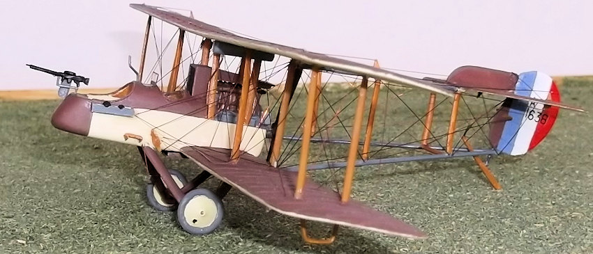
The lower surfaces, nacelle sides and wheel discs were clear
doped linen, the top surfaces and nacelle nose, top and rear of the
underside were PC 12. In fact it is not certain whether DH 1A's were
painted in these colours according to C. Overs in the DatatFile, but
Munson shows this colour in his illustration, and I think it
reasonable that some covering would have been used particularly in
the desert sun. The ammunition boxes, booms, fuel tank and tyres
were grey. The struts were natural wood. I hand painted the roundels
and rudder stripes and the serials came from an Almarks set.
When the painting is compete cement the four outer wing struts
into the holes on the lower wing. The put small drops of glue into
the holes in the upper wing and carefully lower the top wing on to
the lower wing and fin. The fin should have the pin on the bottom
inserted into the V of the lower boom where it is held with
superglue, and the top of the rudder is cemented to the rear of the
fin on the horizontal tail surface. Support this assembly while it
dries out, but also make sure that everything is square. When this
assembly has dried out you can add the inner wing and cabane struts,
and the boom struts. On the starboard forward cabane strut you need
to add a wind generator made from scrap 30 thou card, and on the
port forward cabane strut a fuel pipe from the fuel tank to the top
of the nacelle.
Cut two sets of undercarriage legs from 30 thou card and shape
them to aerofoil section. I cut a small extension to the bottom of
the legs so that I could put in the small cu
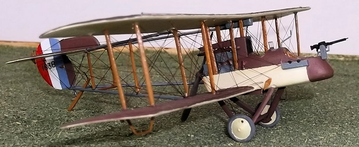
rved
section which supported the axle, rather than drilling a hole as I
sometimes do. The DH 4 axle can be used without modification, as can
the wheels. Cement the legs to the fuselage and the axle between the
legs and set aside to dry. The legs and axle were painted PC 12. I
cut a tail skid from card but did not glue the skid or wheels until
the model was rigged as they are easily damaged. Finally add the
control horns to the fuselage and flying surfaces - these were from
scrap 15 thou card.
I used the same procedure to rig this model as I used with
other pushers: start with the cabane strut wires, then the
front/rear wires between the wing struts, the wires along the rear
of the wings, then the front of the wings, undercarriage, booms,
tail bracing and control wires, wing control wires and last the
anti-drag wires at the rear and then the front. If you are
systematic and work on one side of the model and then do the same
set of wires on the other side for each stage you should avoid
leaving any out. I used copper wire held with superglue. The tail
skid was added as the last item during the rigging process.
Final details can now be added: the
propellor, wheels, underwing skids, machine gun mountings, a machine
gun and cartridge bag if desired, and a windscreen for the pilot.
The observer had a two-piece screen that folded downwards and
forwards but on many aircraft this seem to have been removed, so I
did not include it on my model.
Pushers are not the most popular subjects for modellers but they
are not as difficult to build or rig as some think. Obviously
experience with conversions is needed before attempting a project
like this but the effort is worthwhile because it enables the
modeller to add a lesser known type to their collection. Pusher
types in general formed an important part of RFC equipment in the
first three years of WW1 because they did not need an interruptor
gear to fire forwards. In addition they were robust and because many
types had been ordered in large numbers early in the war but were
slow in delivery, they were used long after they had been made
obsolete by later tractor designs with interruptor mechanisms, or
they were diverted to secondary fronts where older equipment was
still in use. This was one of the easier pushers that I have
converted or built from scratch, and its elegant lines make it an
interesting and attractive model. It was a forerunner of many more
successful designs to come from G. de Haviland's drawing board,
including the DH 4 which used DH 1/1A wings.
Datafile no 148: The AMC DH 1/1A, C
Overs, Albatros Publications
Fighters Attack and Training Aircraft 1914-1918, K Munson, Blandford.

 Consequently de Haviland produced a prototype
powered by the 70 hp Renault V8 engine. This first flew in January 1915
and an order for 49 machines followed. Called the DH 1 this machine took
a long time to get into production like all other British aircraft at
this time and as a result it was not widely adopted by the RFC because
the FE 2b had already been ordered in large numbers and had a better
overall performance.
  ready to carve, but then I gave up modelling! Since then the Datafile No 148 has been published and at last
reasonably accurate drawings of this machine have become readily
available in 1/72 scale. Having finished the Vickers Gunbus conversions
from the Airfix DH 4 (see previous articles), I thought that it was time
that I attempted this long postponed project and added this little known
pusher design to my collection. I was able to make use of the Datafile
and I would advise readers to do so if they wish to convert one of these
models as there is much useful information, good photos and accurate
drawings. If you want to build either the DH1 or 1A you will need a new
engine - a Renault in the case of the DH1 or a 120 hp Beardmore for the
DH 1A. I do not know of a source for a Renault engine but I was able to
acquire an Aeroclub Beardmore, although these are becoming hard to
obtain. You could of course scratch build either engine, (as I did with
the Beardmore for the FE2b - see previous article), as the drawings in
the Datafile would be a good starting point for the Renault and would
probably provide enough information for most modellers. For either
aircraft you will need a DH 4: I started with the Airfix kit as it was
inexpensive and reasonably accurate. I used the wings, struts, wheels,
axle and machine gun from the kit and a propellor from the Airfix Avro
504 which I happened to have in the spares box, but you could easily
modify the propellor from the DH 4.
 s basic - a floor, seats,
control column and rudder bar, some stringers on the sides and bulkheads
between the cockpits and behind the pilot's seat. The interior sides
were painted in clear doped linen, the floor, bulkheads and curved upper
parts of the fuselage wood, and the nose in aluminium. When you are
happy with the interior details cement the two fuselage halves together
and fill and rub down the joints: do not worry too much about under the
engine compartment as most of this will be removed later.
 Final details can now be added to the nacelle. Drill two holes
for the front undercarriage legs, and make two ammunition boxes for
the observer from 10 thou card and cement to the nacelle sides. I
made a small air intake to fit on the starboard side just behind the
pilot's cockpit from 10 thou card and another intake underneath the
nacelle, also from 10 thou card. Coamings were added to the cockpits
from stretched sprue.
  The lower wing of the DH 4 needs the centre section removing.
Lay the fuselage nacelle on the plan and butt one of the wings to
the fuselage so that the correct span can be marked on the wing tip.
Mark the new tip shape ensuring that the correct span is achieved
and then cut and reshape the new tip. Repeat this operation for the
other lower wing. Fill the strut holes, aileron grooves, moulding
dimples and remove the bomb racks. Rub down the wing ribs and filler
and then add two small pieces of 20 thou card to the cut out in the
centre section as per the upper wing. Reshape the cut-out to the new
larger size and sand the trailing edge of the card to a knife edge.
Add new ribs as described above and scribe in the new ailerons.
Finally re-align the anhedral as per the upper wing.
 Cut the fin/rudder from 20thou card and the horizontal tail
surface from the same material, and then file both to aerofoil
section. Scribe the hinge lines and then a small hole in the front
lower part of the fin to take a short length of thin rod - this will
form the support for the tail skid and help to hold the fin in place
in the V of the lower booms. A small upper fin needs to be cut to
sit on top of the horizontal surface. Add ribs to both sides of the
the fin and rudder, and to the upper surface of the horizontal
stabilizer.
 rved
section which supported the axle, rather than drilling a hole as I
sometimes do. The DH 4 axle can be used without modification, as can
the wheels. Cement the legs to the fuselage and the axle between the
legs and set aside to dry. The legs and axle were painted PC 12. I
cut a tail skid from card but did not glue the skid or wheels until
the model was rigged as they are easily damaged. Finally add the
control horns to the fuselage and flying surfaces - these were from
scrap 15 thou card.