| KIT #: | |
| PRICE: | |
| DECALS: | None |
| REVIEWER: | Chris Peachment |
| NOTES: |
Made from sheet plastic, rod and
strut. |

| HISTORY |
I first came across this machine while
watching Those Magnificent Men in their Flying Machines.
It was one of the many new and eccentric designs tried
out by Count Ponticelli, while being watched by his terminally anxious wife and
their vast number of children. By the end she has finally managed to deter him
from any more dangerous exploits by declaring herself pregnant with yet another
bambino, and like a good and doting Italian father he agrees to stay at home.
It was originally
known as the Kitchen Annular biplane, after a flying pioneer, John Kitchen of
Lancashire, who had patented ideas for several circular wing aircraft. He built
one of them and housed it at Famine Point, in Lancashire, though it is likely
that it did not fly before being bought in 1910 by Cedric Lee a wealthy textile
manufacturer from Manchester, in the North of England. He brought in G Tilghman
Richards, who was also a member of the Manchester Aero club.
It underwent a
number of tests and modifications, incorporating some of Richard's theories. It
overturned in a ditch and while it was being repaired a gale blew down the
hangar in 1911, and destroyed it. From then on, Richards' theories were tested
on models and a full size glider version of the same aircraft.
 For the film, it was constructed as a
non-flying full scale model, and the few brief
sequences in which it is shown flying were done by
suspending the model from wires.
After the film, the biplane was placed in storage in Newark Museum, in
the Midlands, and in February 2000 the museum placed the replica on loan with
the Shoreham Airport Historical Association, who commenced the restoration work.
It now resides in Newark Air Museum, and there are plenty of photos of
this machine in situ, on a number of websites. The modeller should beware
though, as a number of changes seems to have been made, mostly around the
cockpit area. The restored version has the equivalent of a toddler's high chair
for the pilot. Though from what I can gather from the few fuzzy pictures of the
original, the setup was rather different. Of course there would have been
constant modification to the original, and so you must make up your own mind.
The fuel tank on the replica has pointed ends, whereas pictures of the
original suggest rounded ends.
Also the museum version has two castering
tail wheels, presumably for ease of handling. The original had two skids. Again
check your references, while bearing in mind that this period of flying employed
a suck-it-and-see approach, with aircraft
undergoing much tinkering and many changes to the
airframe all the time.
I can't see any reason why this shouldn't have flown successfully. Circular wings are nothing new, and have flown later in history on aircraft such as The Vought Flying Pancake. And unlike many of its contemporaries this one even has lateral control, with two single-acting ailerons on the front inter-plane struts. The engine was a 50hp Gnome seven-cylinder air-cooled rotary, which was a well tried unit.
| CONSTRUCTION |
There are no
scale plans that I could find, and very little information on dimensions.
However I found out from Newark that the diameter of the wings is 20 feet and
that of the interior radius 10 feet, and so all else flowed from that starting
point. Some plans were sketched following these measurements.
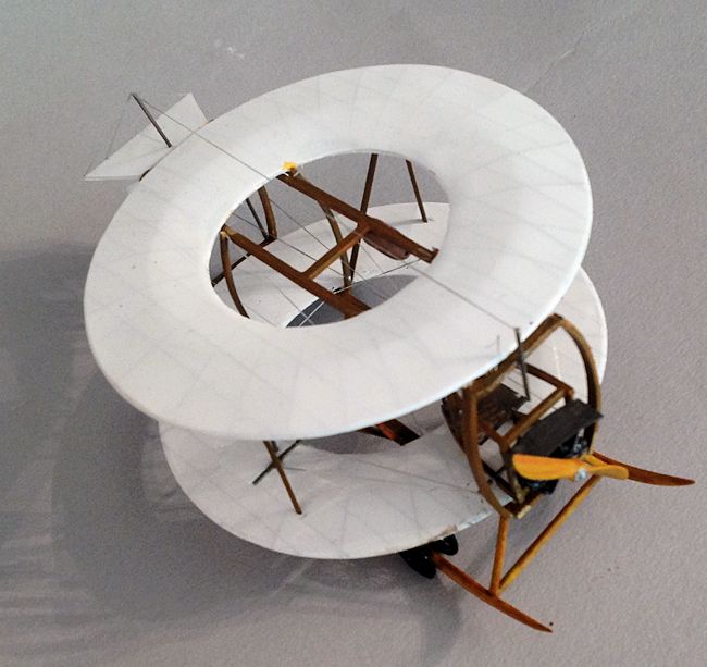
I began with the
wings, the bottom surfaces of which I cut from 10 thou plastic sheet, using a
circle cutter. This is a very handy device, rather like a pair of dividers, but
with a cutting blade at one of the tips. I got mine from a local artist supplies
shop. For the top surfaces I used five thou card, cut to slightly larger
dimensions to allow for trimming. Note that they have ribs going fore and after,
but also radiating out from the centre to the circumference. These were scored
underneath using a black biro and steel rule.
 Then some thick plastic rod was bent
into a circle and glued to the bottom surface at
the mid chord point. Then the upper surfaces were glued
over this, held in place with clothes pegs, and when dried trimmed to fit. A
little filler was needed here to cover for glue indentations on the thin card.
Spray them white.
Once the wings were done, then it is
largely a matter of bridge building.
Anyone who ever constructed cranes or bridges from
Meccano (aka Erector Sets in the US) as a kid will have no trouble.
You will see that the frame of the Newark replica is
made of squared timber, which looks unlikely, but seems to accord with period
photos. I varied it a little here and there by inserting some strut shaped rods,
but mostly used square strips cut from the edge of sheet card.
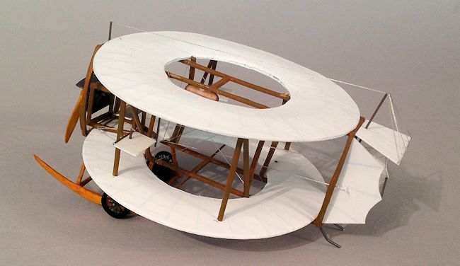
Two ladder frames
were made with connecting struts at the mid points. These were then glued to the
underside of each wing. The vertical connected struts were measured with
dividers and duly inserted. Note that the four main interwing struts are bowed
outwards.
Carry on inserting struts and rods all
over the place until you can't see the wood from the trees.
You will feel like you are actively doing something for
deforestation.
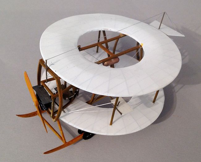
The nacelle for
the pilot's seat is torpedo shaped with a square front for the engine. The seat
is a simple oblong, with a dark brown cushion from putty. Control rods were made
from thin rod, with a rudder bar below.
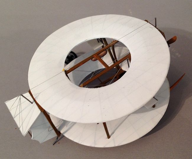
 The tail was cut
from 10 thou card and scored with pencil, before being sprayed white. The fins
have two small control horns and are joined by an interconnecting rod as can be
seen. The elevator has a long control horn, made from rod. The control horns
were all connected to the pilot's controls by elastic thread. As was the
elevators multiple wires. The elevator control is a separate “joystick” mounted
on the front of the upper frame. Paint the all the frames wood brown, with a
topcoat of clear orange.
The two undercarriage bars were carved
and sanded from thick card, and mounted on circular struts. The fuel tank was
made from thick sprue, sanded down at either end, painted bronze, and glued to
the port upper ladder frame. Four wire wheels were made from Eduard etched WWI
spoke wheels, and the tires were made of solder wrapped around
a paintbrush of the right diameter.
This is a lot quicker than trying to ream out the centre
of old plastic wheels with a motor tool. And a lot safer for your fingertips
too.
Finally an engine
was found from the spares box, mounted on a square backing plate and glued to
the frame, with a shaped cover above, presumably to prevent too much oil
spraying all over the pilot.
Incidentally,
most pilots of this period suffered drastic stomach upset, brought on by
inhaling castor oil which was the chief engine lubricant. No wonder most flights
only lasted a short time.
As always the
finishing touch is a prop from the Big Bag of Props, sanded a little to shape,
painted brown, with an etched boss at the front, and mounted at ten to four.
| CONCLUSIONS |

And they do say that if you go to Area
51 on nights when the moon is full you may see a strange pair of white discs
hurtling across the sky in close formation at all of 20 knots, with a cry in a
faint British accent from the cockpit:
“They all laughed when I said it would fly,
but who's laughing now?”
| REFERENCES |
https://www.flickr.com/photos/roblovesey/10382689084/
http://www.bapc.org.uk/html/bapc_photos_1.html
http://3elgarion.deviantart.com/art/Lee-Richards-Annular-Biplane-I-195525150
http://jetphotos.net/viewphoto.php?id=6551945
August 2014
If you would like your product reviewed fairly and fairly quickly, please contact the editor or see other details in the Note to Contributors.